
Systems and methods for electrosurgical treatment of obstructive sleep disorders

a technology of sleep disorder and electrosurgical treatment, applied in the field of electrosurgical treatment of obstructive sleep disorder, can solve the problems of prone to excessive bleeding, difficult control, cumbersome measures, etc., and achieves the effect of sufficient surface area, easy to cause bleeding, and easy control

Inactive Publication Date: 2006-11-07
ARTHROCARE
View PDF270 Cites 380 Cited by
  • Summary
  • Abstract
  • Description
  • Claims
  • Application Information

AI Technical Summary

Benefits of technology

[0009]The systems and methods of the present invention are particularly useful for ablation, cutting and hemostasis of tissue for gross tissue removal in the mouth and throat, and for treating obstructive sleep disorders, such as snoring or sleep apnea. The present invention removes obstructive tissue within the mouth and throat with a novel, precise process that involves lower temperatures than conventional RF devices and lasers used for such tissue removal. Consequently, the gross tissue removal of the present invention provides significantly less collateral tissue damage, which results in less post-operative pain and faster healing than conventional procedures.
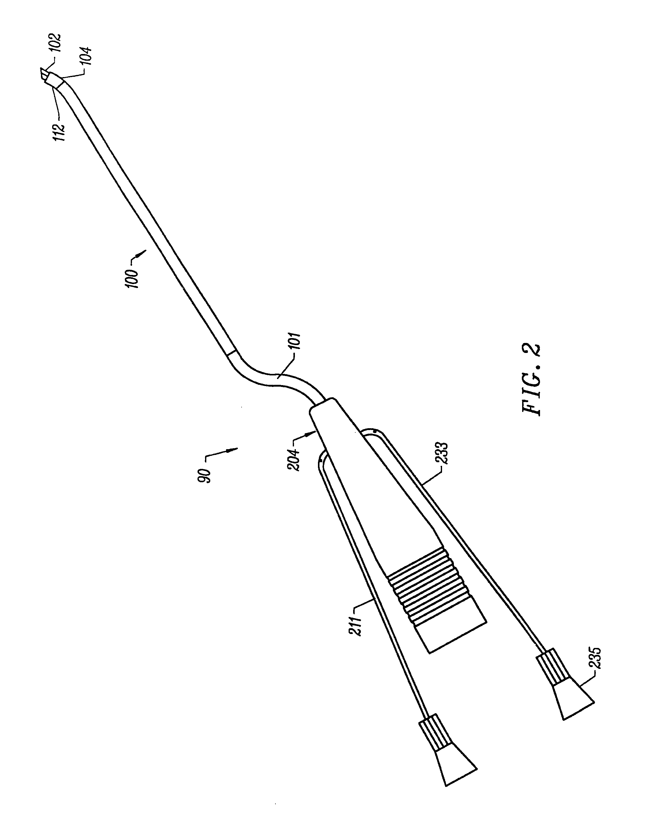
[0016]In one embodiment, the electrode terminal(s) are designed for cutting tissue; i.e., they typically have a distal edge or point, and they are aligned with each other to form a linear cutting path through the tissue. For some applications, such as tonsillectomies or UPPP's that involve tonsil removal, the target tissue is extremely vascular and prone to excessive bleeding that is often difficult to control during the procedure. According to the present invention, in some embodiments, the electrode assembly will have sufficient surface area to effectively coagulate and seal the severed blood vessels within the target tissue. In an exemplary embodiment, the electrode assembly comprises one or more loop electrodes aligned with each other, and having a distal edge for cutting along a substantially linear cutting path. The loop configuration of the electrode terminals provides additional exposed surface area for coagulation of severed blood vessels after the tissue has been removed. In a specific configuration, the electrode assembly comprises a pair of outer electrode terminals and an inner loop electrode aligned with each other to form a linear cutting path. The outer electrode terminals have a relatively small distal end region that forms an effective cutting configuration, while the inner loop electrode provides sufficient exposed surface area for effective coagulation.

Problems solved by technology

These measures are sometimes helpful, but rarely completely effective.
These measures are cumbersome, uncomfortable and difficult to use for prolonged periods of time.
In particular, CPAP devices, which act essentially as a pneumatic “splint” to the airway to alleviate the obstruction, may last for the entire patient's lifetime, and typically requires close to 100% usage of the device while sleeping and napping.
While these procedures are effective, the risk of surgery in some patients is often prohibitive.
In addition, UPPP and LAUP procedures performed with conventional electrocautery or laser devices typically generate excessive bleeding and extreme post-operative pain which may be unacceptable to the patient.
Of course, such monopolar devices suffer from the disadvantage that the electric current will flow through undefined paths in the patient's body, thereby increasing the risk of unwanted electrical stimulation to portions of the patient's body.
This current, however, may inadvertently flow along body paths having less impedance than the defined electrical path, which will substantially increase the current flowing through these paths, possibly causing damage to or destroying surrounding tissue or neighboring peripheral nerves.

Method used


Image

  • Systems and methods for electrosurgical treatment of obstructive sleep disorders
  • Systems and methods for electrosurgical treatment of obstructive sleep disorders
  • Systems and methods for electrosurgical treatment of obstructive sleep disorders

Examples


Embodiment Construction

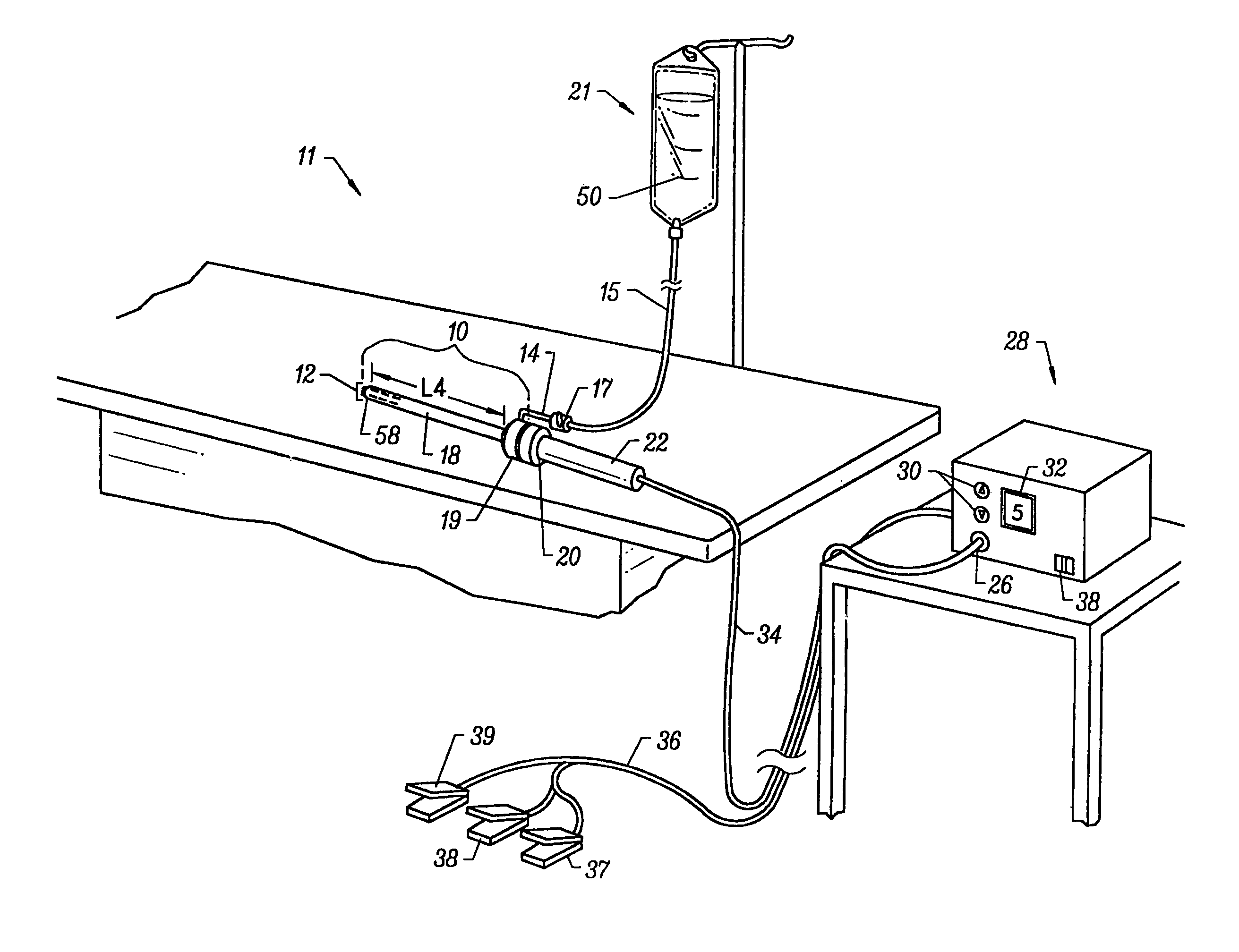
[0045]The present invention provides systems and methods for selectively applying electrical energy to a target location within or on a patient's body, particularly including tissue in head and neck, such as the ear, mouth, pharynx, larynx, esophagus, nasal cavity and sinuses. These procedures may be performed through the mouth or nose using speculae or gags, or using endoscopic techniques, such as functional endoscopic sinus surgery (FESS). These procedures may include the removal of swollen tissue, chronically-diseased inflamed and hypertrophic mucus linings, polyps and / or neoplasms from the various anatomical sinuses of the skull, the turbinates and nasal passages, in the tonsil; adenoid, epi-glottic and supra-glottic regions, and salivary glands, submucus resection of the nasal septum, excision of diseased tissue and the like. The present invention may also be useful for cosmetic and plastic surgery procedures in the head and neck. For example, the present invention is particula...


PUM

PropertyMeasurementUnit
Electrical conductivityaaaaaaaaaa
Electric potential / voltageaaaaaaaaaa

Abstract

The present invention provides systems and methods for selectively applying electrical energy to a target location within the head and neck of a patient's body, particularly including tissue in the ear, nose and throat. The present invention applies high frequency (RF) electrical energy to one or more electrode terminals in the presence of electrically conductive fluid to remove and / or modify the structure of tissue structures. The present invention is particularly useful for treating sleep obstructive disorders, such as sleep apnea and snoring.

Description

RELATED APPLICATIONS[0001]The present invention is a divisional application of U.S. patent application Ser. No. 09 / 136,079, filed Aug. 18, 1998 now U.S. Pat. No. 6,086,585, which is a continuation-in-part of U.S. patent application Ser. No. 09 / 083,526, filed May 22, 1998, now U.S. Pat. No. 6,053,172 which is a continuation-in-part of Ser. No. 08 / 990,374, now U.S. Pat. No. 6,109,268 filed Dec. 15, 1997, which is a continuation-in-part of application Ser. No. 08 / 485,219 filed Jun. 7, 1995, now U.S. Pat. No. 5,697,281, the complete disclosures of which are incorporated herein by reference for all purposes.[0002]The present invention is related to commonly assigned co-pending U.S. patent application Ser. No. 09 / 058,571, filed on Apr. 10, 1998 and U.S. patent application Ser. No. 09 / 054,323, filed on Apr. 2, 1998, U.S. patent application Ser. No. 09 / 010,382, filed Jan. 21, 1998, and U.S. patent application Ser. No. 09 / 032,375, filed Feb. 27, 1998, U.S. patent application Ser. No. 08 / 977,...

Claims


Application Information

Patent Timeline
IPC IPC(8): A61B18/18A61B17/00A61B18/00A61B18/14A61F2/02A61M1/00A61M3/02
CPCA61B18/1402A61B18/148A61B18/1482A61B18/1485A61B18/149A61B18/1492A61B2218/002A61B2218/007A61F2/2493A61M3/0283A61B18/042A61B18/1206A61B2017/00026A61B2017/00084A61B2017/00101A61B2017/00247A61B2018/00029A61B2018/00083A61B2018/00119A61B2018/0016A61B2018/00178A61B2018/00327A61B2018/00392A61B2018/00505A61B2018/00577A61B2018/00583A61B2018/00601A61B2018/00678A61B2018/00702A61B2018/00726A61B2018/00791A61B2018/00827A61B2018/00875A61B2018/00982A61B2018/1213A61B2018/124A61B2018/1253A61B2018/126A61B2018/1273A61B2018/1407A61B2018/1467A61B2018/1472A61B2018/162A61B2018/165
Inventor HOVDA, DAVID C.ELLSBERRY, MARIA B.EGGERS, PHILIP E.THAPLIYAL, HIRA V.
Owner ARTHROCARE
Learn More