
Brake power generator for a hydraulic motor vehicle brake system, and hydraulic motor vehicle brake system

a technology for brake systems and brake power generators, which is applied in braking systems, couplings, position/direction control, etc., can solve the problems of relatively long pedal strokes, relatively complicated construction, and inability to respond to the brake system after a relatively long pedal stroke, so as to promote the characteristic of the brake system. good

Inactive Publication Date: 2006-10-31
LUCAS AUTOMOTIVE GMBH
View PDF18 Cites 19 Cited by
  • Summary
  • Abstract
  • Description
  • Claims
  • Application Information

AI Technical Summary

Benefits of technology

Ensures reliable and rapid response of the brake system in emergency situations by allowing direct mechanical coupling between the force input element and primary piston, providing a familiar resistance feedback to the driver and improving the overall response characteristic of the brake system.

Problems solved by technology

The solution according to EP 1 003 658 B1 admittedly has the desired effect of an extensive mechanical uncoupling of force input element and primary piston during normal operation and moreover presents a rapid response characteristic in the case of the emergency operating mode, but its construction is relatively complicated and entails exact and therefore laborious manufacture, which adds to the cost thereof.
EP 1 003 658 B1 shows a further embodiment (FIG. 1), which, whilst being of a simple construction, has the drawback that in the emergency operating situation it responds only after a relatively long pedal stroke.
In the event of a defect of the actuating force booster stage, the spring arrangement remains ineffective.
However, for a moment the driver has the unpleasant sensation that the brake pedal may be depressed without resistance.

Method used


Image

  • Brake power generator for a hydraulic motor vehicle brake system, and hydraulic motor vehicle brake system
  • Brake power generator for a hydraulic motor vehicle brake system, and hydraulic motor vehicle brake system
  • Brake power generator for a hydraulic motor vehicle brake system, and hydraulic motor vehicle brake system

Examples


second embodiment

[0048]The second embodiment according to FIG. 3 moreover shows a connection of the tappet 24a to the contact extension 64a that is modified compared to FIG. 2. The tappet 24a at its, in FIG. 3, left end has a pin 108a, onto which a cup spring assembly 110a is mounted. At its free end the tappet is provided with a locking bush 109a, which is fixed thereon and limits the axial displaceability of a stop bush 111a mounted displaceably on the tappet 108a. The stop bush 111a projects axially beyond the locking bush 109a.

[0049]The arrangement in the region of the free end of the tappet 24a operates as follows. During normal operation, the stop bush 111a is held with its left end, as already described more than once, at a distance from the contact extension 64a, namely in such a way that the release gap s is maintained. This is effected by a corresponding pressure build-up in the actuating chamber 100a. However, if such a pressure build-up is not possible, e.g. as a result of an electronic...

third embodiment

[0051]FIG. 4 shows the braking force generator according to the invention, however only in a schematic representation. Once more, for components of an identical type or identical effect the same reference characters as for the description of the first two embodiments are used, only followed by the letter “b”.

[0052]In contrast to the first two embodiments, the braking force generator 12b has, not a hydraulic actuating force booster stage, but a pneumatically actuated actuating force booster stage. This comprises two walls 112b and 114b, which are movable in the screened housing and attached flexibly to the housing 20b by means of bellows-type seals 116b and 118b. The movable wall 112b together with the housing 20b encloses a first vacuum chamber 120b. Between the movable wall 112b and the movable wall 114b a working chamber 122b is delimited. Finally, the movable wall 114b together with the housing encloses a second vacuum chamber 124b. By means of the control valve 92b the two vacuu...


PUM


Abstract

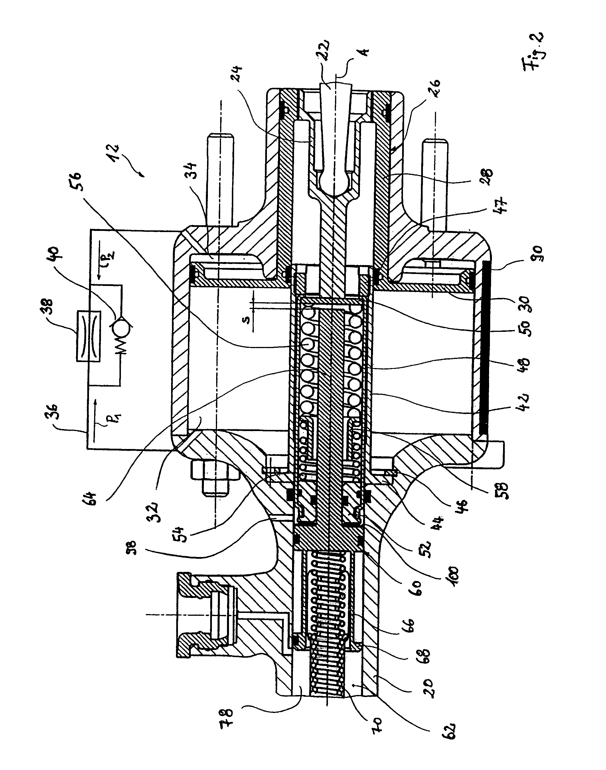
A braking force generator includes a primary piston displaceable in a housing to enclose a primary pressure chamber. A pedal simulation device is connected to the force input element. A pedal actuation detection device detects the pedal actuation and an actuating force booster stage. During normal operation the force input element is mechanically uncoupled from the primary piston, and the actuating force booster stage exerts an actuating force on the primary piston. In the event of failure of the actuating force booster stage the force input element is workingly connectable to the primary piston such that a contact extension extends from the primary piston towards the force input element. During normal operation the contact extension is held by a release gap at a distance from the force input element and in the event of failure of the actuating force booster stage the force input element after travelling the release gap is applied workingly against the contact extension.

Description

CROSS REFERENCE TO RELATED APPLICATIONS[0001]This application is a continuation of International Application No. PCT / EP2004 / 002459 filed Mar. 10, 2004, the disclosures of which are incorporated herein by reference, and which claimed priority to German Patent Application No. 103 11 060.7 filed Mar. 13, 2003, the disclosures of which are incorporated herein by reference.BACKGROUND OF THE INVENTION[0002]The invention relates to a braking force generator for a hydraulic brake system comprising a force input element, which is connected to a brake pedal, a housing and a primary piston displaceable in the housing, wherein the primary piston together with the housing encloses a primary pressure chamber for generation of a hydraulic brake pressure, a pedal simulation device connected to the force input element, a pedal actuation detection device for detecting a pedal actuation and an actuating force booster stage for exerting an actuating force on the primary piston, wherein during normal op...

Claims


Application Information

Patent Timeline
Patent Type & Authority Patents(United States)
IPC IPC(8): B60T13/00F15B7/00B60T8/40B60T13/14
CPCB60T8/4077B60T13/145B60T13/147
Inventor OHLIG, BENEDIKTGIERING, WILFRIEDMICHELS, ERWINSTEINHEUER, HERBERT
Owner LUCAS AUTOMOTIVE GMBH
Learn More