
Methods, systems and computer program products for calibration of microscopy imaging devices

a microscopy and imaging device technology, applied in the field of microscopy imaging apparatus, can solve the problems of poor light budget of confocal microscope, inability to successfully image three-dimensional structures, and inability to reject out-of-focus detail of conventional light microscopes

Inactive Publication Date: 2006-10-03
THALES SA
View PDF6 Cites 26 Cited by
  • Summary
  • Abstract
  • Description
  • Claims
  • Application Information

AI Technical Summary

Benefits of technology

[0010]As a second aspect, embodiments of the present invention are also directed to a method of calibrating an imaging system using a phase-voltage technique. In these embodiments, the imaging system includes: a light source; a substrate for supporting an object; a patterning mask that generates a substantially periodic spatial pattern on the object; a phase shifter that adjusts the position of the patterning mask to shift the position of the pattern on the object, the phase shifter including a piezoelectric device that adjusts the position of the mask responsive to an applied voltage; a detector that detects images of the object; and an analyzer that analyzes at least three images of the object, each of which represents a different spatial shift of the pattern, t...

Problems solved by technology

With a conventional light microscope three-dimensional structures typically cannot be successfully imaged.
A conventional light microscope is unable to reject out-of-focus detail.
Unfortunately, the light budget of confocal microscopes is generally poor when incoherent light sources are used.
Laser scanning confocal microscopes can achieve a very shallow depth of focus, but typically require expensive apparatus and an illuminating / imaging pinhole through which the laser light is focused.
In practice this has been found to be almost impossible to achieve.
Unfortunately, conventional microscopy imaging masks utilized, for example, by Wilson et al. can leave residual patterning in the final image.
Such residual patterning is undesirable since it raises doubt as to whether the pattern is part of the specimen or an artifact of the imaging process.
However, when imaged through band-limited systems (such as an optical system) the resultant image has residual patterns.
One issue that can arise with full-focus techniques, and particularly those that utilize a set of sinusoidally-varying stripes in the pattern, is related to the calibration of the system.
Generally speaking, microscopy errors can occur if the system is not precisely calibrated.

Method used


Image

  • Methods, systems and computer program products for calibration of microscopy imaging devices
  • Methods, systems and computer program products for calibration of microscopy imaging devices
  • Methods, systems and computer program products for calibration of microscopy imaging devices

Examples


example 1

Phase Calibration

[0076]This calibration method is based on a measurement of the phases (rather than being an optimization technique). Below is provided a theoretical background and a detailed procedure for this calibration technique.

A. Intensity Cross Section

[0077]The basis for the phase calibration technique is the intensity cross section and its Fourier Transform. Although this cross section and its transform are familiar, they are reviewed here for completeness. Shown in FIG. 6 is a cross section of a single intensity frame taken across the grid. In the calibration this data will be the average of 10 or so such cross sections for the purpose of noise reduction. Note that 210 points=1024 points are considered in order to leverage Fast-Fourier Transform (FFT) software.

B. The Fourier Transform of the Intensity

[0078]These sections provide a basic coverage of the FFT of the intensity cross section that will be used for the phase calibration. The phase of the FFT is used for the calibr...

example 2

Merit Function Calibration

[0136]The fidelity of the calibration can be determined by analyzing the second harmonic content of the residual lines. It has been found that the calibration error is the only thing that produces second harmonic residual lines. Therefore, the second harmonic content of the residual lines can be a metric function for the calibrations. The algorithm could be a damped optimization routine based on this merit function.

A. Calibration Merit Function Theory

[0137]Because the fidelity of the calibration is known to directly affect the second harmonic content of the imaging system data, what follows is a detailed look at this function vs. detuning of the calibration phases of the imaging system. A detailed procedure for evaluating the merit function from actual imaging system data is also discussed in this section.

[0138]1. Merit Function for Small Detuning

[0139]FIG. 17 shows the behavior of the second harmonic (normalized to the fundamental) for small deviations fro...


PUM


Abstract

An imaging system on which a calibration method is practiced includes: a light source; a substrate for supporting an object; a patterning mask that generates a substantially periodic spatial pattern on the object; a phase shifter that adjusts the relative position of the patterning mask and object to shift the position of the pattern on the object; a detector that detects images of the object; and an analyzer that analyzes at least three images of the object, each of which represents a different spatial shift of the pattern, the analyzer being configured to remove the spatial pattern from the images to generate an optically sectioned image of the object. The calibration method includes: calibrating the position of the mask relative to the substrate via a phase-voltage technique; calibrating the position of the mask relative to the substrate via a merit function technique; and operating the calibrated imaging system.

Description

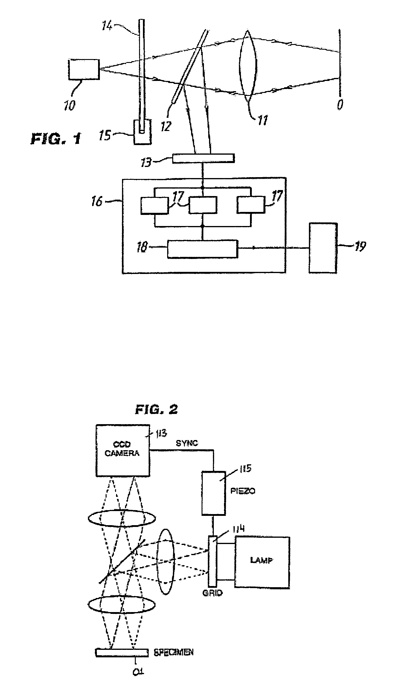
FIELD OF THE INVENTION[0001]The present invention relates generally to microscopy imaging apparatus and an imaging method for generating an image which generally contains only in-focus detail, and more specifically to calibration techniques for same.BACKGROUND OF THE INVENTION[0002]With a conventional light microscope three-dimensional structures typically cannot be successfully imaged. Ordinarily, the resultant image consists of a sharp image of an in-focus region of a three-dimensional structure as well as defocused images of the structures above and below the in-focus region. A conventional light microscope is unable to reject out-of-focus detail.[0003]Confocal microscopes have been developed which optically section a three-dimensional structure to provide in-focus images of individual layers or strata of the structure. These individual layers can be subsequently combined to form an in-focus three-dimensional image of the complete volume structure. Unfortunately, the light budget...

Claims


Application Information

Patent Timeline
IPC IPC(8): G02B27/40G02B27/64G01D5/36
CPCG02B21/244G02B21/365
Inventor ZINTER, J. ROBERTCHAKMAKJIAN, STEPHEN
Owner THALES SA
Learn More