
High purity fluid delivery system

a fluid delivery system and high purity technology, applied in liquid transferring devices, process and machine control, instruments, etc., can solve problems such as inability to accept the surface of the wafer, alter or remove critical wafer structures, and bio-technology fluid delivery problems

Inactive Publication Date: 2006-10-03
EMERSON ELECTRIC CO
View PDF40 Cites 85 Cited by
  • Summary
  • Abstract
  • Description
  • Claims
  • Application Information

AI Technical Summary

Problems solved by technology

Many industries such as semiconductor, pharmaceutical, and bio-technology experience fluid delivery problems due to the typically low flow rates, the use of abrasive and aggressive chemical fluids, and the need for contaminant free, accurate, compact, and real-time fluid delivery and / or blending systems.
Over-polishing the wafer can result in altering or removing critical wafer structures.
Conversely, under-polishing of the wafer can result in an unacceptable wafer surface.
It is a problem in some applications that the instruments used to control the process are a source of contaminants to the process material.
This is undesirable for use in systems where material an ultra high of purity must be delivered to a user's application.
For example, the metal flow tube of a typical Coriolis flowmeter can be a source of contaminates.
This released material can cause the chips on a semi-conductor wafer to be defective.
While the clean flow path non-intrusive characteristic of peristaltic pumps is acceptable for CMP applications, the use of these pumps to attempt to control fluid flow rate is very inaccurate since they are operated open-loop with no flow measurement feedback
The key difference between the lithography process and the spin-on deposition is that any defect in the film (such as a void, bubble or particle) is now permanently embedded in the structure of the semiconductor and could result in non-functioning devices and a financial loss for the semiconductor producer.
Problems associated with currently available fluid delivery systems used in processes such as CMP and spin-on applications include the inability to provide closed loop flow measurement, the inability to provide an accurate fluid delivery rate based on changing head pressure of the pump system, variances in the volume of tubing used in the pump, and pulsations from the pump.
Other problems associated with current fluid delivery systems involve contamination of the fluid from shedding tubing particles.
While all of the foregoing fluid properties can be measured using a combination of various instruments such as differential pressure transmitters, viscometers, densitometers, pressure transmitters, temperature elements or a combination of the instruments and a control system to calculate the fluid property values, the use these instruments can be expensive, have significant space requirements, require increased maintenance, and provide a greater potential for fluid leakage and process contamination.
In addition, blending based on a volumetric basis is generally unacceptable since typical blending formulas are based on molar ratios.
Unfortunately, the current batch production method can result in too much or too little of the final product being available when needed.
Since having too little product available would shut a process down, extra product is always produced, meaning some product will be left over and not used.
Since these products often have a limited shelf life (e.g. several hours) this excess product must be disposed of.
This disposal is costly for several reasons.
The product is typically uses very expensive chemicals, and the fluid mixture can often be very hazardous meaning it must be disposed of in a controlled and costly manner.

Method used


Image

  • High purity fluid delivery system
  • High purity fluid delivery system
  • High purity fluid delivery system

Examples


Embodiment Construction

[0039]Illustrative embodiments of the invention are described below. In the interest of clarity, not all features of an actual implementation are described in this specification. It will of course be appreciated that in the development of any such actual embodiment, numerous implementation-specific decisions must be made to achieve the developers' specific goals, such as compliance with system-related and business-related constraints, which will vary from one implementation to another. Moreover, it will be appreciated that such a development effort might be complex and time-consuming, but would nevertheless be a routine undertaking for those of ordinary skill in the art having the benefit of this disclosure.

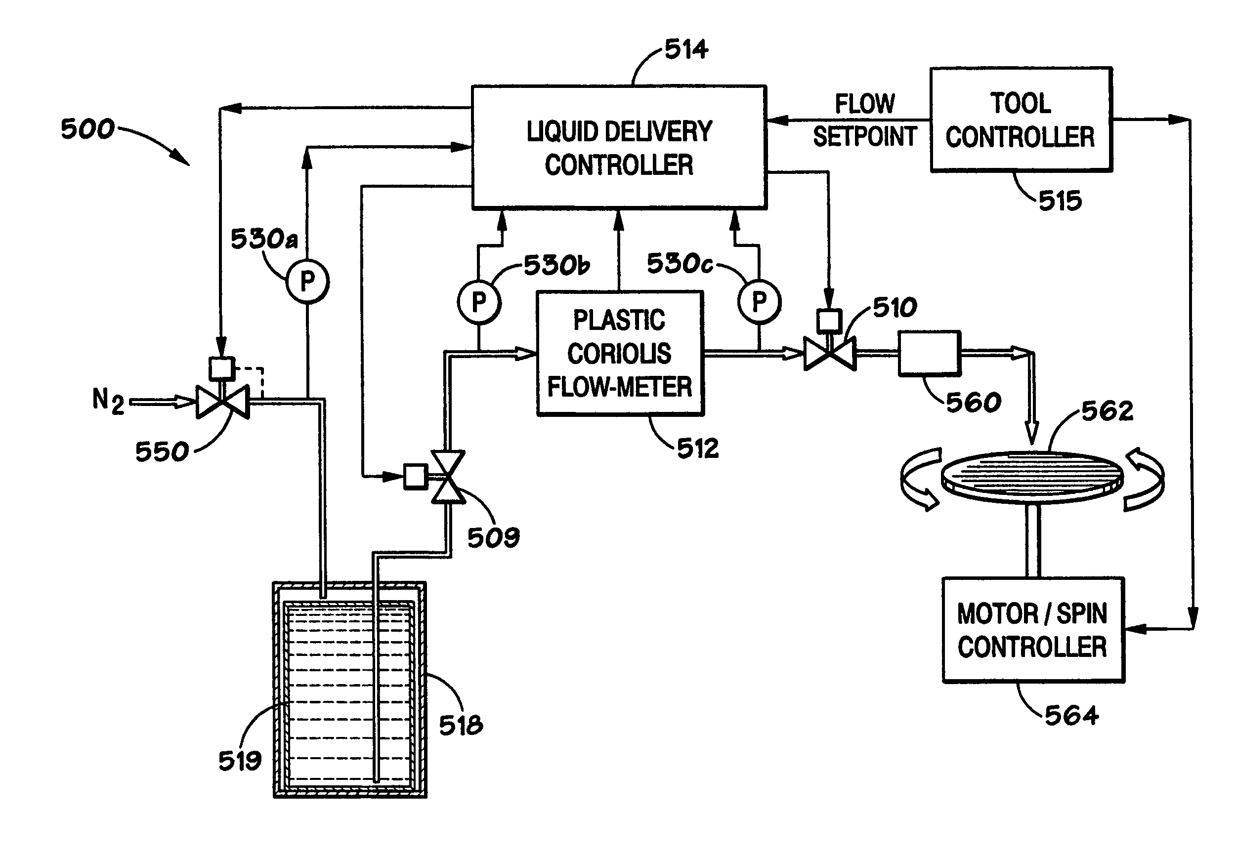
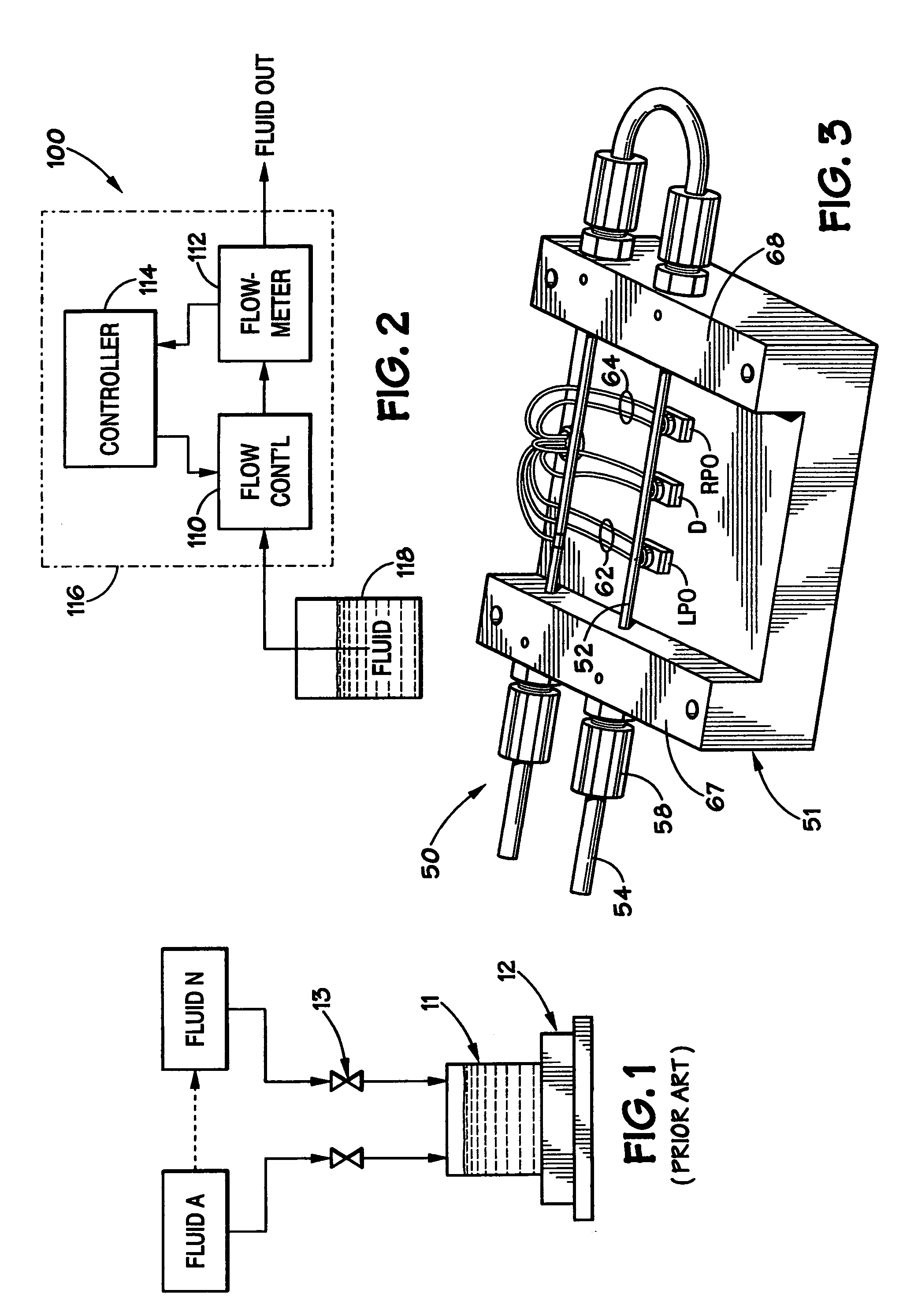
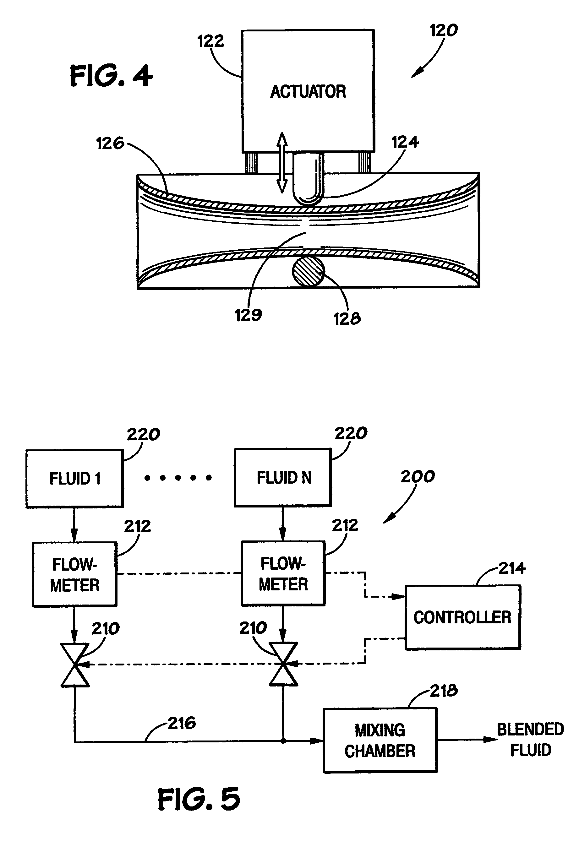
[0040]FIG. 2 schematically illustrates a fluid delivery system 100 in accordance with exemplary embodiments of the invention. The mass flow-based delivery system 100 is suitable, for example, to control the flow of fluid to a tool or a work piece supported by a tool, such as a po...


PUM

PropertyMeasurementUnit
thickaaaaaaaaaa
pressureaaaaaaaaaa
flow rateaaaaaaaaaa

Abstract

A fluid delivery system includes a flow control device and a Coriolis mass flowmeter in fluid communication with the flow control device. The Coriolis flowmeter has a flow-tube made of a high-purity plastic material, such as PFA, making the delivery system suitable for high purity applications. A controller provides a control output signal to the flow control device, which may comprise a pinch valve, so as to vary the flow control device output in response to a setpoint signal and measurement signals received from the flowmeter.

Description

CROSS-REFERENCE TO RELATED APPLICATIONS[0001]This application is a divisional of U.S. patent application Ser. No. 09 / 995,067, filed on Nov. 26, 2001, now abandoned which is incorporated by reference in its entirety.BACKGROUND OF THE INVENTION[0002]1. Field of the Invention[0003]The present invention relates generally to fluid delivery systems, and more particularly, to improved fluid delivery systems and methods that are suitable for the direct application of ultra-pure fluids to a wafer surface in processes such as CMP, photolithography and dielectric processes.[0004]2. Description of Related Art[0005]Many industries such as semiconductor, pharmaceutical, and bio-technology experience fluid delivery problems due to the typically low flow rates, the use of abrasive and aggressive chemical fluids, and the need for contaminant free, accurate, compact, and real-time fluid delivery and / or blending systems.[0006]Generally the semiconductor industry uses the word “tool” to refer to a syst...

Claims


Application Information

Patent Timeline
Patent Type & Authority Patents(United States)
IPC IPC(8): G05D7/06G01F1/00G01F1/84G01L19/06
CPCG01F1/8413G01F1/8422G01F1/8495G05D7/0635Y10T137/7761Y10T137/7759Y10T137/3127
Inventor SUND, WESLEY E.DILLE, JOSEPH C.BARGER, MICHAEL J.PAWLAS, GARY E.
Owner EMERSON ELECTRIC CO
Learn More