
Sternum closure device

a closure device and sternum technology, applied in the field of sternum closure devices, can solve the problems of obstructing the separation process of the sternum closure device, easy to be removed, and difficult to sever the sternum with a bone saw

Inactive Publication Date: 2009-09-17
AESCULAP AG
View PDF20 Cites 160 Cited by
  • Summary
  • Abstract
  • Description
  • Claims
  • Application Information

AI Technical Summary

Benefits of technology

[0008]An inner contact element, which consists at least partially of a biocompatible plastics material, can also be severed when severing the sternum, whether with the bone saw or, after the introduction of a bone separating cut, with scissors or a similar instrument. After separation of the inner contact element, the sternum parts can easily be spread apart, so that a body access is created.
[0011]The holding projections, on pressing the inner holding element onto the inner face of the sternum, are pressed into the bone substance and thus secure the inner contact element to the inner face of the sternum. These holding projections should preferably consist of metal as they have to exert large forces. It is therefore advantageous if the inner contact element, on the one hand, has holding projections made of metal, but, on the other hand, has a centre part made of plastics material, which can be severed again in the described manner in the case of a re-operation.

Problems solved by technology

If a renewed opening of the sternum becomes necessary with the separation thereof into two sternum parts, the parts of the sternum closure device possibly obstruct the separating process, however.
This applies, in particular, to the inner contact elements which abut the inner face of the sternum and cannot easily be removed.
In the case of the outer contact elements, there is the possibility of lifting these off, but in the case of the inner contact elements there is no possibility of access, however, and it is therefore difficult to sever the sternum with a bone saw.

Method used


Image

  • Sternum closure device
  • Sternum closure device
  • Sternum closure device

Examples


Embodiment Construction

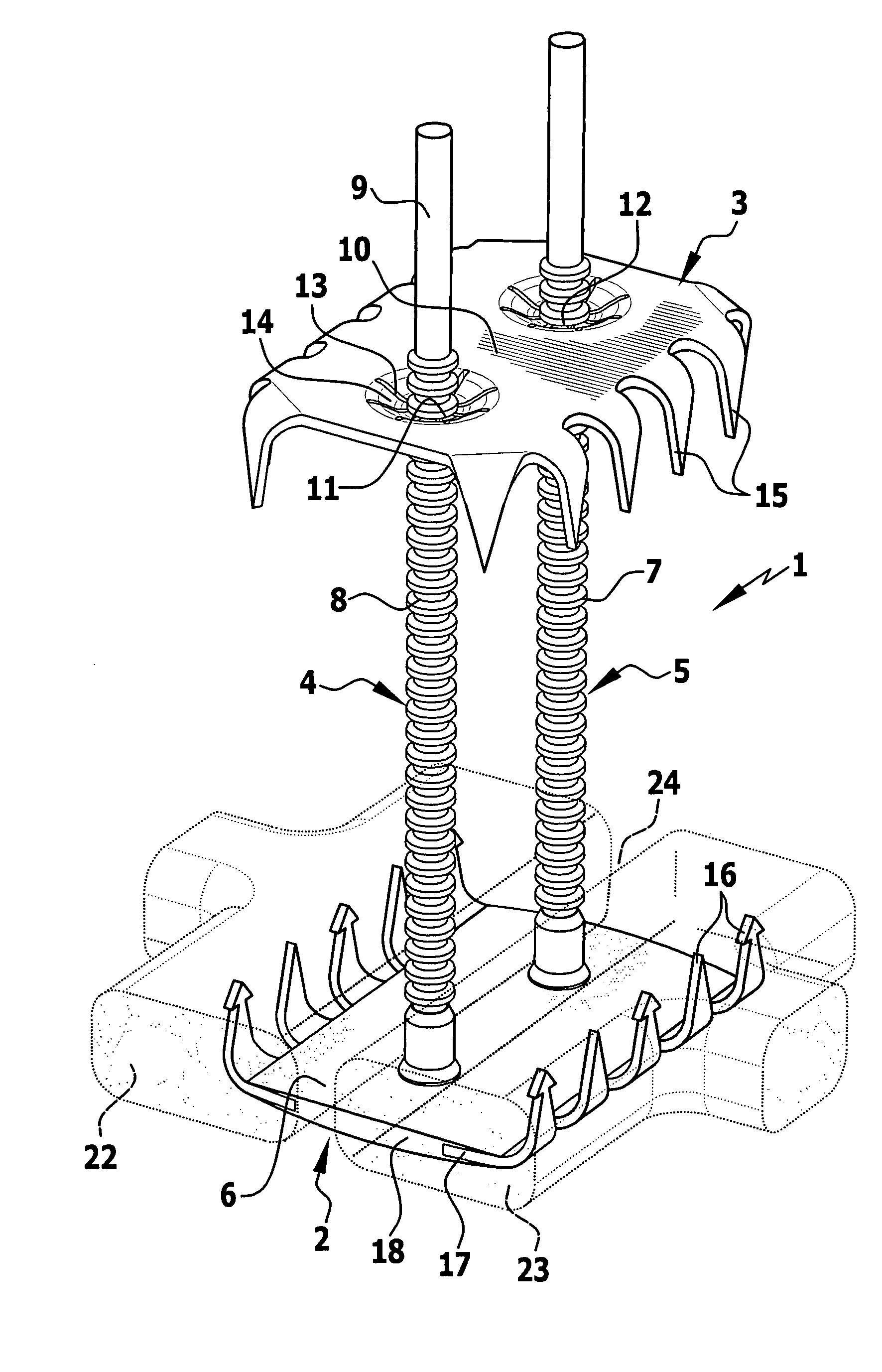
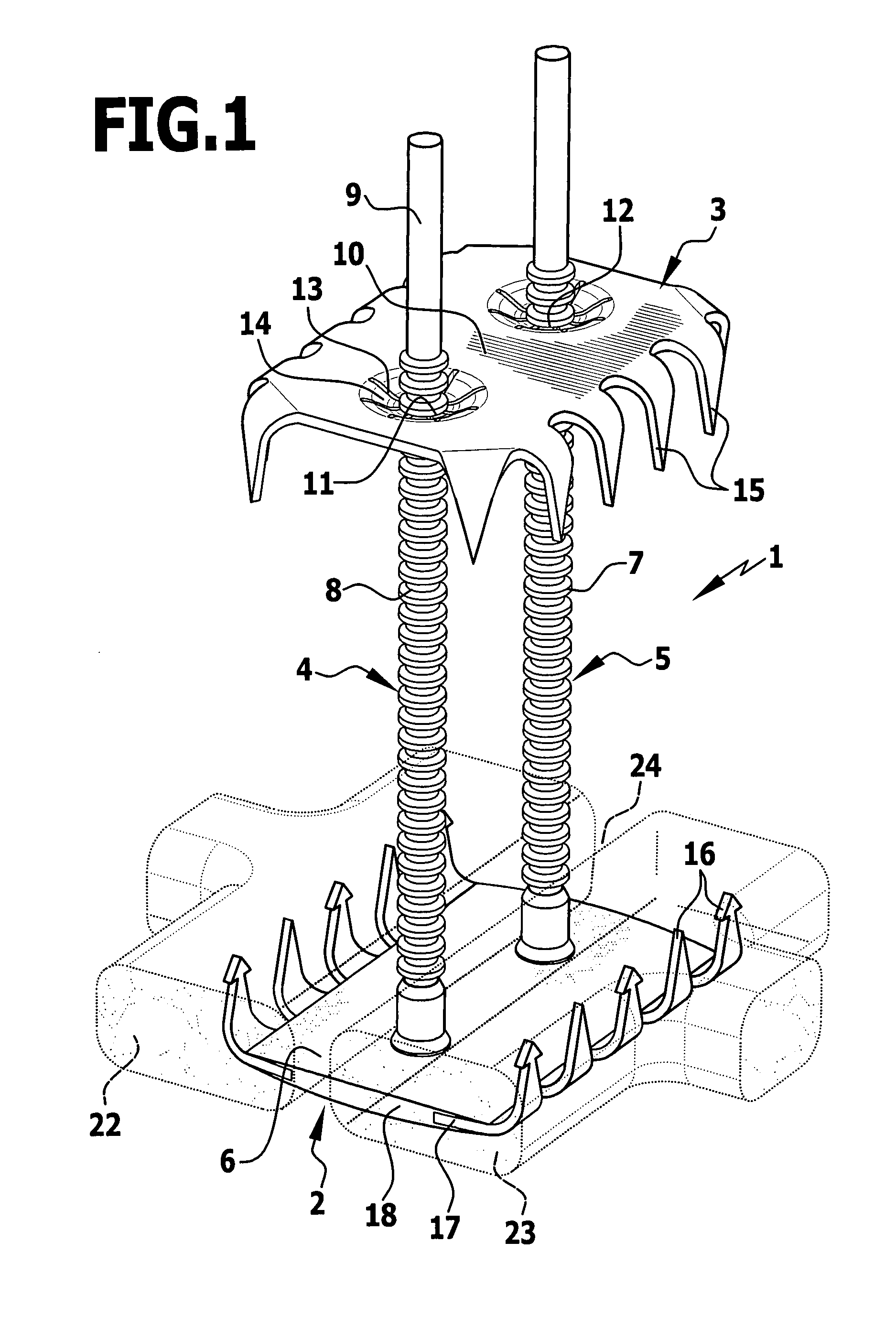
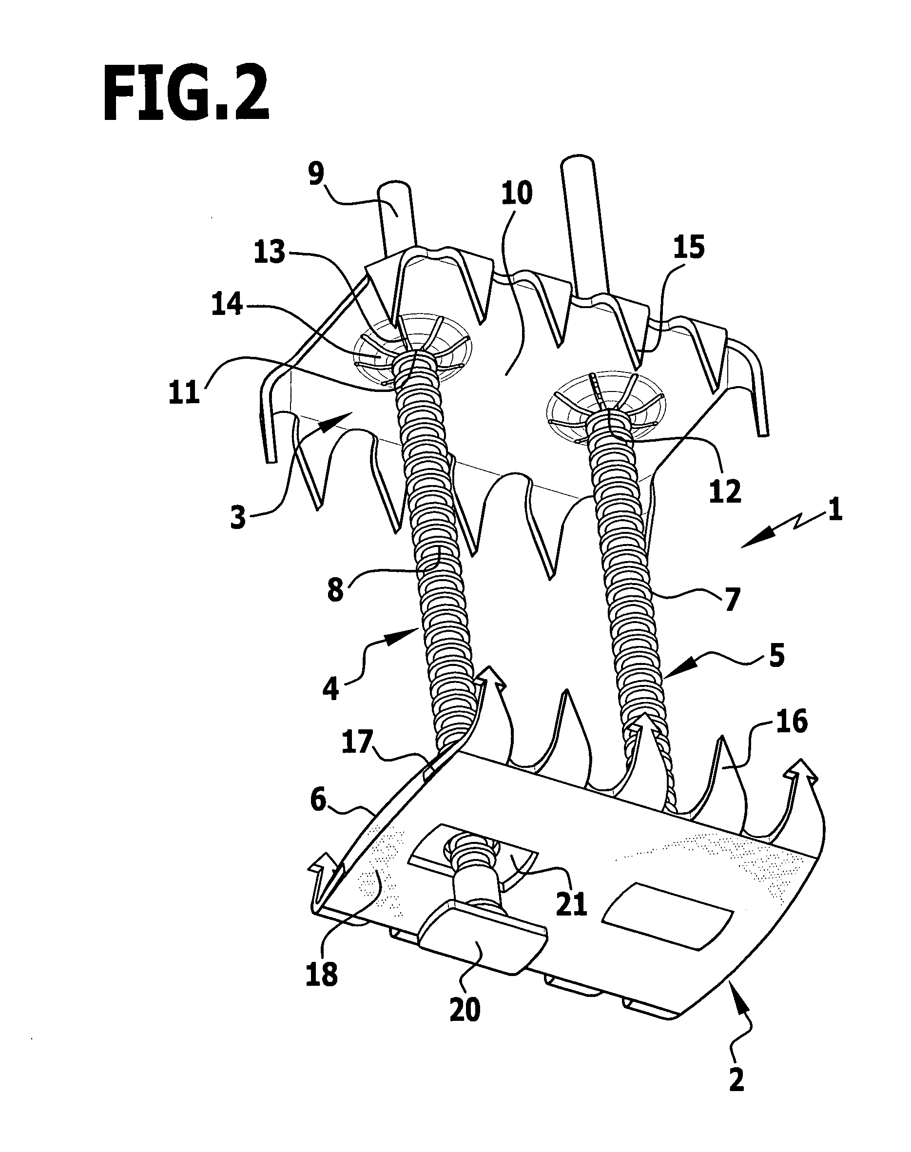
[0023]The sternum closure device 1 shown in FIGS. 1 to 3 has an inner contact element 2 and an outer contact element 3, which are connected to one another by means of two latching pins 4, 5, acting as a clamping element, and can be clamped relative to one another. The latching pins 4, 5 are held on the plate-shaped inner contact element 2, that is substantially rectangular in the embodiment shown, in such a way that they project perpendicularly from the upper side of the inner contact element 2 and this upper side forms a substantially level contact face 6.

[0024]The two latching pins 4, 5, above the inner contact element 2, carry a relatively large number of peripheral ribs 7 and they form therewith a latching portion 8, adjoined toward the free end of the latching pins 4, 5 by a respective extending portion 9 with a smooth outer wall. Placed on the extending portions 9 of the two latching pins 4, 5 is the outer contact element 3, which consists of metal and has an approximately rec...


PUM


Abstract

In a sternum closure device for securing two sternum parts to be connected to one another, comprising an inner contact element to abut the inner face of the sternum, at least one clamping element secured thereto and projecting transversely therefrom, and comprising an outer contact element for abutment on the outer side of the sternum and which can be clamped by means of the clamping element guided through the intermediate space between the sternum parts against the inner contact element, in order to reduce the obstruction by the sternum closure device in the event of a renewed separation of the sternum parts, it is proposed that the inner contact element consists at least partially of a biocompatible plastics material.

Description

[0001]This application is a continuation of international application number PCT / EP2007 / 006846 filed on Aug. 2, 2007.[0002]The present disclosure relates to the subject matter disclosed in international application PCT / EP2007 / 006846 of Aug. 2, 2007, which is incorporated herein by reference in its entirety and for all purposes.BACKGROUND OF THE INVENTION[0003]The invention relates to a sternum closure device for securing two sternum parts to be connected to one another, comprising an inner contact element to abut the inner face of the sternum, at least one clamping element secured thereto and projecting transversely therefrom, and comprising an outer contact element for abutment on the outer side of the sternum and which can be clamped by means of the clamping element guided through the intermediate space between the sternum parts against the inner contact element.[0004]A sternum closure device of this type is described, for example, in DE 103 26 690 B4. With the aid of a sternum cl...

Claims


Application Information

Patent Timeline
IPC IPC(8): A61B17/68
CPCA61B17/8076A61B2017/00004A61B17/809A61B17/823
Inventor MORALES, PEDROWEISSHAUPT, DIETERLUTZE, THEODORDWORSCHAK, MANFREDEIJSMAN, LEON
Owner AESCULAP AG
Learn More