
Method and apparatus for manufacturing polymer fiber shells via electrospinning

a technology of electrospinning and polymer fiber shell, which is applied in the direction of auxillary shaping apparatus, filament/thread forming, prosthesis, etc., can solve the problems of reduced functionality, reduced mechanical and tensile strength of grafts, and difficult production of polymer fiber shells suitable for use as vascular grafts

Inactive Publication Date: 2006-09-26
NICAST LTD
View PDF106 Cites 36 Cited by
  • Summary
  • Abstract
  • Description
  • Claims
  • Application Information

AI Technical Summary

Benefits of technology

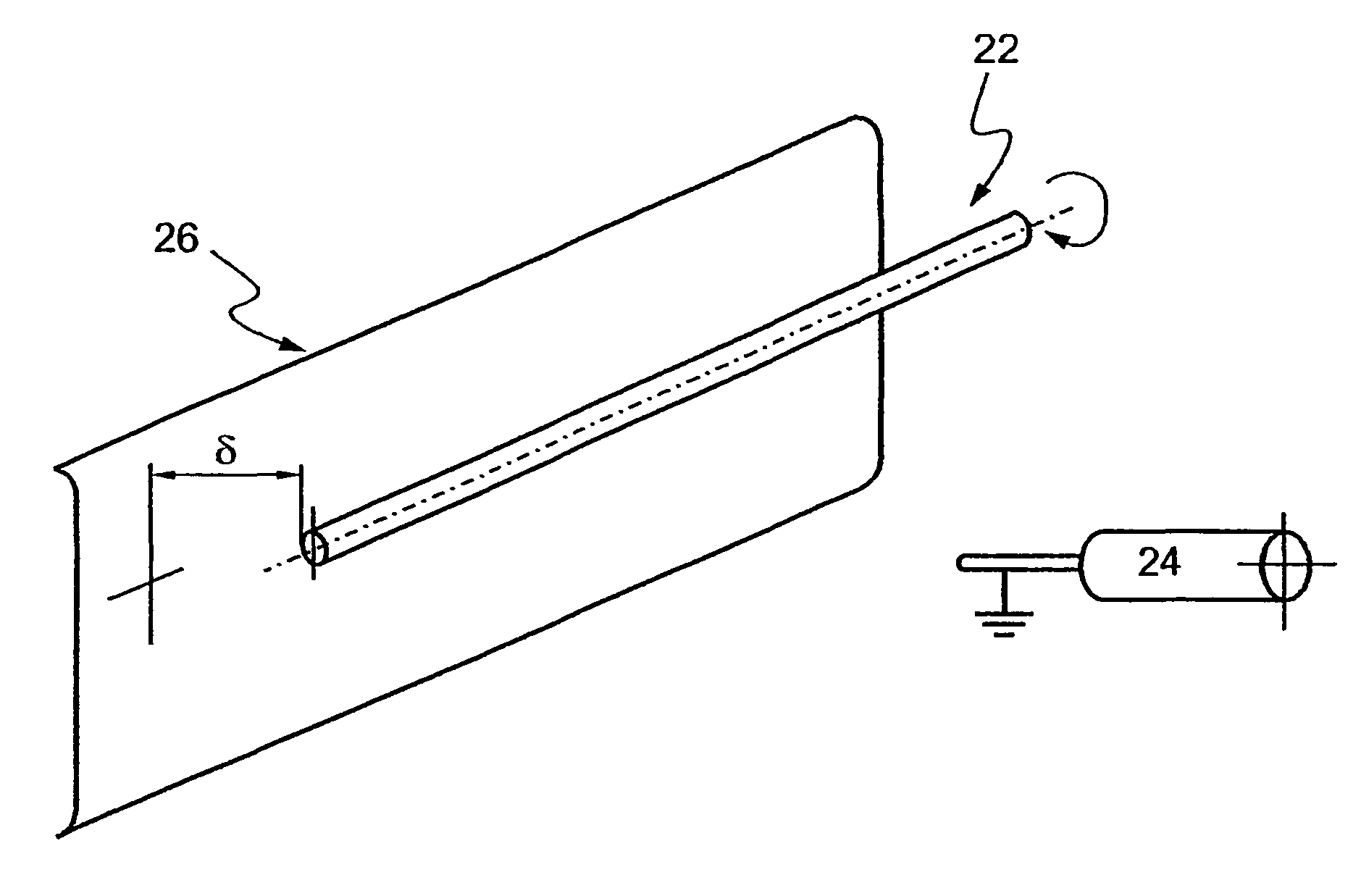
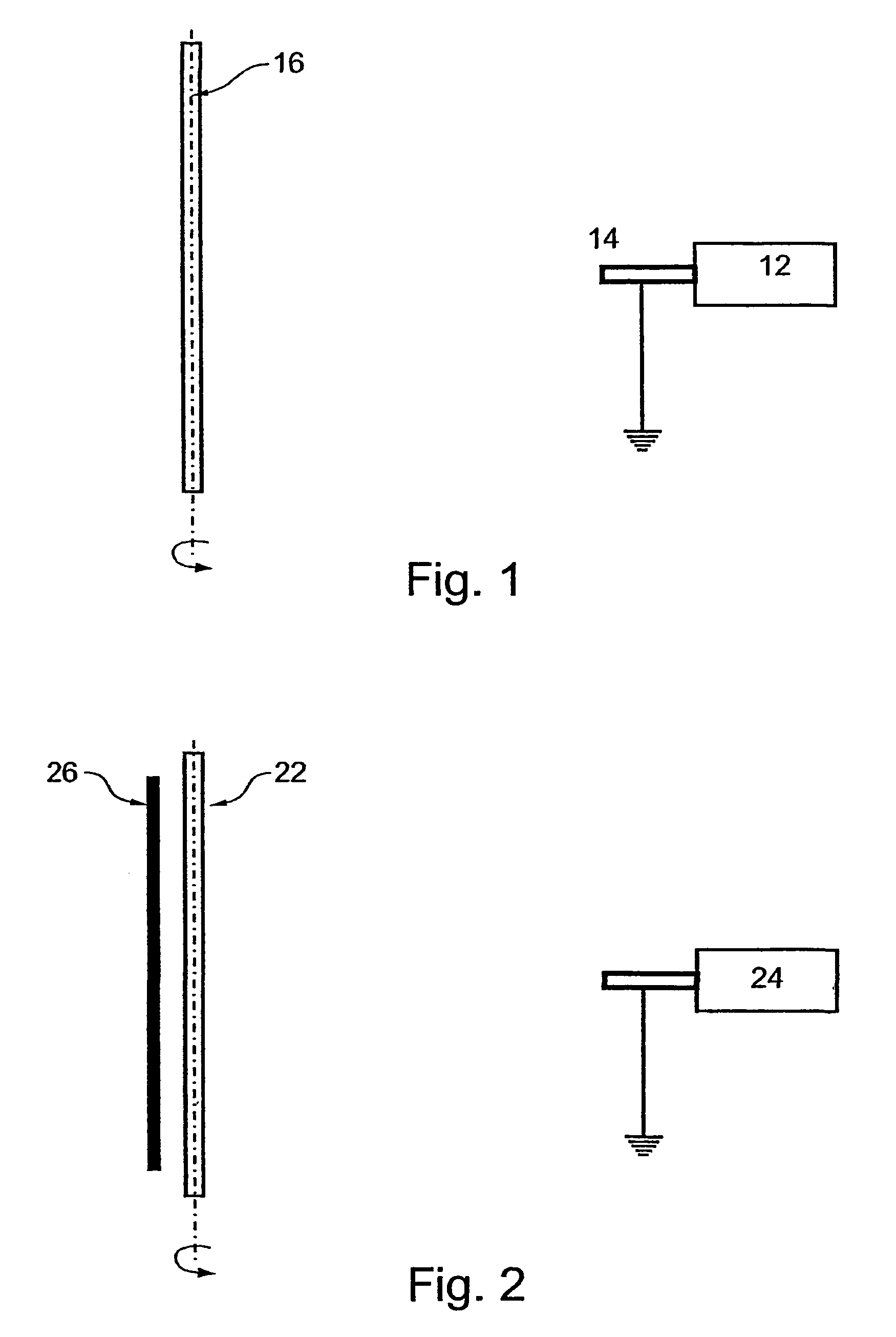
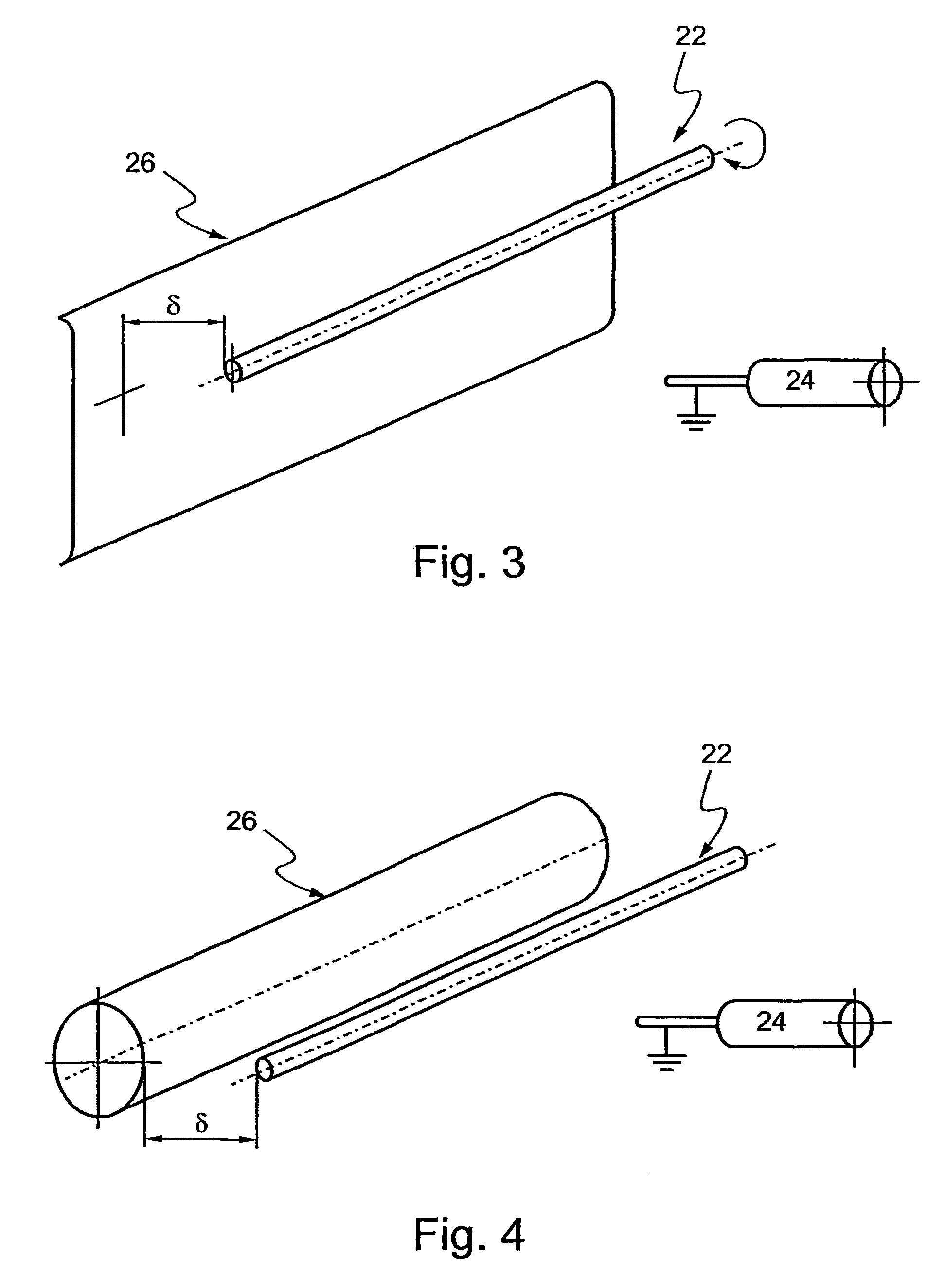
[0022]According to still further features in the described preferred embodiments the subsidiary electrode serves to minimize a volume charge generated between the dispenser and the precipitation electrode.
[0041]According to yet another aspect of the present invention there is provided an apparatus for manufacturing a polymer fiber shells from liquefied polymer, the apparatus comprising: (a) a dispenser, for: (i) charging the liquefied polymer thereby providing a charged liquefied polymer; and (ii) dispensing the charged liquefied polymer; and (b) a precipitation electrode being at a potential relative to the dispenser thereby generating an electric field between the precipitation electrode and the dispenser, the precipitation electrode being for collecting the charged liquefied polymer drawn by the electric field, to thereby form the polymer fiber shell thereupon, wherein the precipitation electrode is designed so as to reduce non-uniformities in the electric field.

Problems solved by technology

Production of polymer fiber shells suitable for use as vascular grafts is particularly difficult, since such grafts must withstand high and pulsatile blood pressures while, at the same time, be elastic and biocompatible.
However, increasing the porosity of vascular grafts leads to a considerable reduction of the mechanical and tensile strength of the graft, and as a consequence to a reduction in the functionality thereof.
Such structural fiber formation considerably reduces the radial tensile strength of a spun product, which, in the case of vascular grafts, is necessary for withstanding pressures generated by blood flow.
However, such methods suffer from the above inherent limitations which limit the use thereof when generating intricate profile fiber shells.
Hence, although electrospinning can be efficiently used for generating large diameter shells, the nature of the electrospinning process prevents efficient generation of products having an intricate profile and / or small diameter, such as vascular grafts.
In particular, since porosity and radial strength are conflicting, prior art electrospinning methods cannot be effectively used for manufacturing vascular grafts having both characteristics.

Method used


Image

  • Method and apparatus for manufacturing polymer fiber shells via electrospinning
  • Method and apparatus for manufacturing polymer fiber shells via electrospinning
  • Method and apparatus for manufacturing polymer fiber shells via electrospinning

Examples


example 1

Axial Covering Using Conventional Electrospinning Method

[0112]Reference is now made to FIG. 7, which is an example of non-randomized covering of thin mandrels via conventional electrospinning. A 3-mm cylindrical mandrel was covered by polycarbonate fiber using prior art electrospinning approaches. FIG. 7 is an electron microscope image of the final product, in which axial fiber orientation is well evident. Due to non-uniformities in the electric field, the fibers, while still in motion in the inter-electrode space, are oriented in conformity with the field configuration, and the obtained tubular structure exhibits axial orientation of fibers, and as such is characterized by axial, as opposed to radial strength.

example 2

Random Covering Using Flat Subsidiary Electrode

[0113]An apparatus constructed and operative in accordance with the teachings of the present invention incorporating a flat subsidiary electrode positioned 20 millimeters from the mandrel and having the same potential as the mandrel was used to spin a polycarbonate tubular structure of a 3 mm radius. As is evident from FIG. 8, the presence of a subsidiary electrode randomizes fibers orientation.

example 3

Polar-Oriented Covering Using Flat Subsidiary Electrode

[0114]An apparatus constructed and operative in accordance with the teachings of the present invention incorporating a flat subsidiary electrode positioned 9 millimeters from the mandrel and being at a potential difference of 5 kV from the mandrel was used to spin a polycarbonate tubular structure of a 3 mm radius.

[0115]As illustrated by FIG. 9, reduction of equalizing electrode-mandrel distance results in polar-oriented covering. Thus, by keeping subsidiary electrode and mandrel within a relatively small distance, while providing a non-zero potential difference therebetween, leads to slow or no fiber charge dissipation and, as a result, the inter-electrode space becomes populated with fiber which are held statically in a stretched position, oriented perpendicular to mandrel symmetry axis. Once stretched, the fibers are gradually coiled around the rotating mandrel, generating a polar-oriented structure.


PUM

PropertyMeasurementUnit
diameteraaaaaaaaaa
diameteraaaaaaaaaa
diameteraaaaaaaaaa

Abstract

An apparatus for manufacturing a polymer fiber shell from liquefied polymer is provided. The apparatus includes: (a) a precipitation electrode being for generating the polymer fiber shell thereupon; (b) a dispenser, being at a first potential relative to the precipitation electrode so as to generate an electric field between the precipitation electrode and the dispenser, the dispenser being for: (i) charging the liquefied polymer thereby providing a charged liquefied polymer; and (ii) dispensing the charged liquefied polymer in a direction of the precipitation electrode; and (c) a subsidiary electrode being at a second potential relative to the precipitation electrode, the subsidiary electrode being for modifying the electric field between the precipitation electrode and the dispenser.

Description

RELATED PATENT APPLICATION[0001]This application is a National Phase Application of PCT / LL01 / 01168 International Filing Date 17 Dec. 2001, which claims priority from U.S. patent application No. 09,982,017 filed 19 Oct. 2001, which claims priority from U.S. Provisional patent application Nos. 60,276,956 filed 20 Mar. 2001 and 60,256,323 filed 19 Dec. 2000.FIELD AND BACKGROUND OF THE INVENTION[0002]The present invention relates to a method and apparatus for manufacturing polymer fiber shells via electrospinning.[0003]Polymer fiber shells such as tubular shaped products, are used in the medical industry for various utilities including esophageal grafts, vascular grafts, stent coats and like.[0004]Numerous methods for manufacturing polymer fiber shells suitable for medical applications are known in the art, including, for example, various injection molding methods, mandrel assisted extrusion or formation and various weaving techniques.[0005]Production of polymer fiber shells suitable fo...

Claims


Application Information

Patent Timeline
Patent Type & Authority Patents(United States)
IPC IPC(8): B29C41/02A61F2/00A61F2/06A61F2/82A61L15/16A61L17/00A61L27/00A61L27/50A61L27/56B29C67/20C08F2/00D01D5/00D01D5/04D01D5/08D04H1/70D04H3/07D04H3/16
CPCA61F2/06A61F2/82A61F2/91A61L27/507A61L27/56B29C67/20D01D5/0007D01D5/0069D01D5/0092D01D5/18D04H1/70D04H3/07D04H3/16Y10T428/1393A61F2002/072A61F2250/0023A61F2250/0067A61F2210/0076Y10T428/1372Y10T428/13Y10T428/139A61F2/07D04H1/728Y10T442/614
Inventor DUBSON, ALEXANDERBAR, ELI
Owner NICAST LTD
Learn More