
Diversity antenna arrangement

a technology of diversity and antennas, applied in the field of diversity antennas, can solve problems such as antenna design and technique challenges, and achieve the effects of reducing the weight of the antenna arrangement, compact structure, and light weigh

Active Publication Date: 2006-09-19
NOKIA TECH OY
View PDF10 Cites 32 Cited by
  • Summary
  • Abstract
  • Description
  • Claims
  • Application Information

AI Technical Summary

Benefits of technology

The solution achieves a reduction in weight by over 30% and maintains equivalent electrical performance to larger designs, with improved isolation and bandwidth, making it suitable for tiny hand-held mobile phones without compromising radiation characteristics.

Problems solved by technology

This has for one's part created new challenges for antenna design and technique.

Method used


Image

  • Diversity antenna arrangement
  • Diversity antenna arrangement
  • Diversity antenna arrangement

Examples


Embodiment Construction

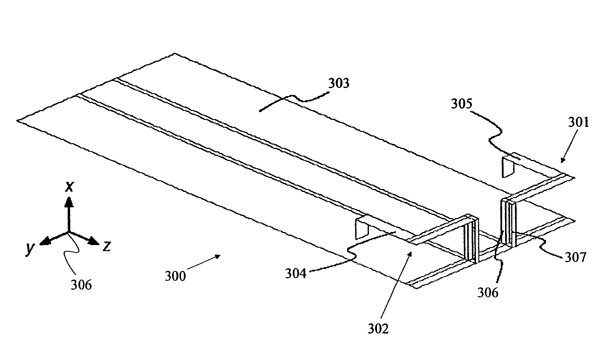
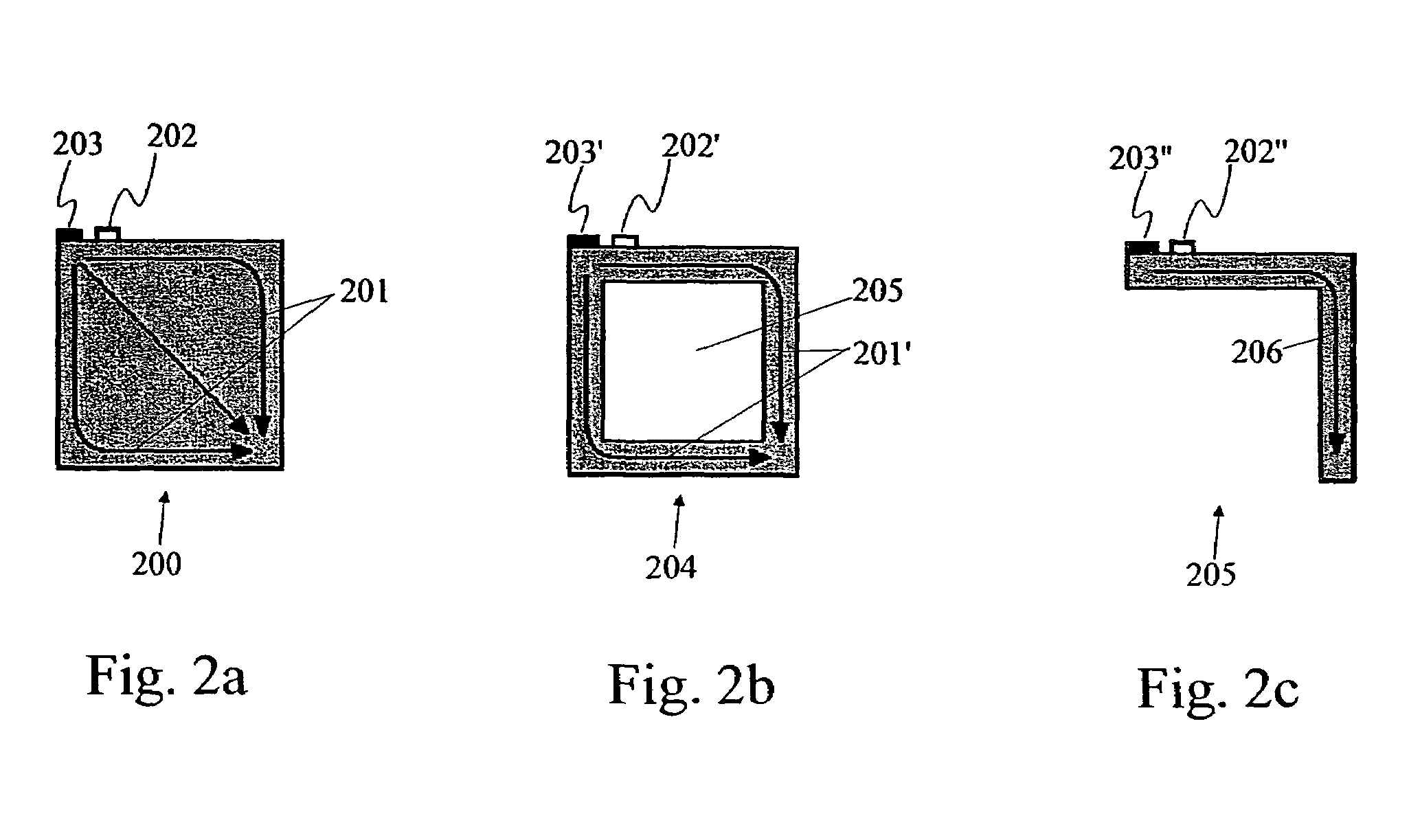
[0031]Some embodiments of the invention provide a diversity antenna arrangement for a mobile station having a general ground element. The diversity antenna arrangement includes at least a pair of antenna elements. Each antenna element comprises a first elongated conductive element. A conductive leg portion is coupled to the first elongated conductive element. The leg portion contains a feed, also known as a feed element or a feed arrangement, for feeding the antenna element against the ground element. Each antenna element has also a second elongated conductive element. The first and the second generally planar elongated conductive elements are transversal to each other and in contact with each other. In some further embodiments, the first and the second generally planar elongated conductive elements are perpendicular to each other. The first and the second generally planar elongated elements and the conductive leg portion are made from a unitary metal part in some embodiments; even ...


PUM


Abstract

There is provided a method of operating, a diversity antenna system and arrangement for a mobile station such as mobile phone having a general ground element, the diversity antenna arrangement including at least a pair of antenna elements. Each antenna element comprises a generally L-shaped radiating element, and a conductive leg portion being operatively coupled to the generally L-shaped radiating element.

Description

TECHNICAL FIELD OF THE INVENTION[0001]The present invention relates to antennas, and more particularly to diversity antennas.BACKGROUND OF THE INVENTION[0002]In the simplest definition of the term, the diversity technique in the design of an antenna is a means of achieving reliable overall system performance through the use of an additional antenna. System performance may be characterized by signal strength, signal to noise ratio, data rate, error rate, or other factors. Of particular importance to wireless data systems is to achieve high data rates with low error rates.[0003]In wireless or radio communications, particularly in mobile radio communications, antenna diversity is a well-known technique for mitigating fast fading caused by multipath signal propagation. In order to obtain diversity gain, at least two signals carrying the same information but with different fading characteristics (low signal correlation) are needed. Polarization diversity, which is one of the commonly use...

Claims


Application Information

Patent Timeline
Patent Type & Authority Patents(United States)
IPC IPC(8): H01Q1/38H01Q1/24H01Q9/04H01Q21/29H04B5/48H04B7/10
CPCH01Q1/243H01Q9/0407H01Q9/0421H04B7/10H01Q21/29H04B5/02H01Q9/0442H04B5/48
Inventor OLLIKAINEN, JANIICHELN, CLEMENSVAINIKAINEN, PERTTI
Owner NOKIA TECH OY
Learn More