
Loop assemblies having a central link

a technology of loop assemblies and links, applied in the direction of walking sticks, dolls, building repairs, etc., can solve the problems of lessened structural stability, and achieve the effect of retaining the strength and stability of the structure, specific favorable properties, and being able to us

Inactive Publication Date: 2006-09-05
HOBERMAN CHARLES
View PDF25 Cites 32 Cited by
  • Summary
  • Abstract
  • Description
  • Claims
  • Application Information

AI Technical Summary

Benefits of technology

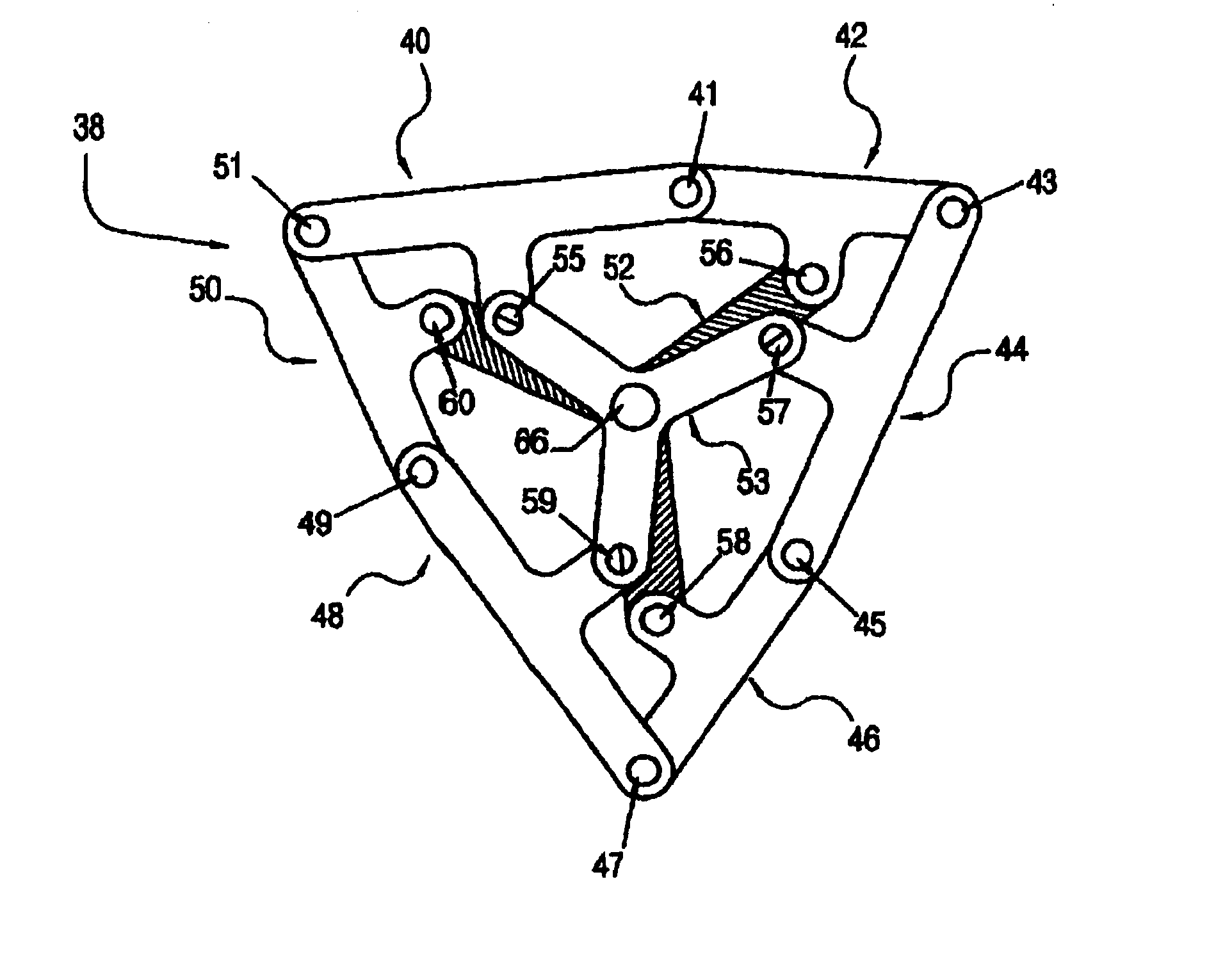
[0011]Structures built in accordance with the subject invention have specific favorable properties, including: a) The ability to use highly rigid materials rather than bending or distortion of the mechanical links, allowing for a smooth and fluid unfolding process; b) The use of compact, structurally favorable and inexpensive joints in the form of simple pivots; c) Retaining the strength and stability of the structure during folding and unfolding since all movement in the structure is due to the actual deployment process, without floppiness in the structure; d) A wide range of geometries; e) Inexpensive manufacture of structures with flexible hinges that are formed continuously with the links themselves; f) Convenient assembly of structures of many different shapes through kits of the necessary parts; g) The ability to create a space-filling structure by arranging linkages in a three-dimensional matrix; h) Structures have additional stability and structural stability because of the central piece, while still retaining its ability to expand and contract; and i) Structures have a central location to provide a means to mechanically drive the entire assembly.

Problems solved by technology

However, at the center of such a ring, a space or void is opened up as the ring expands, resulting in lessened structural stability.

Method used


Image

  • Loop assemblies having a central link
  • Loop assemblies having a central link
  • Loop assemblies having a central link

Examples


Embodiment Construction

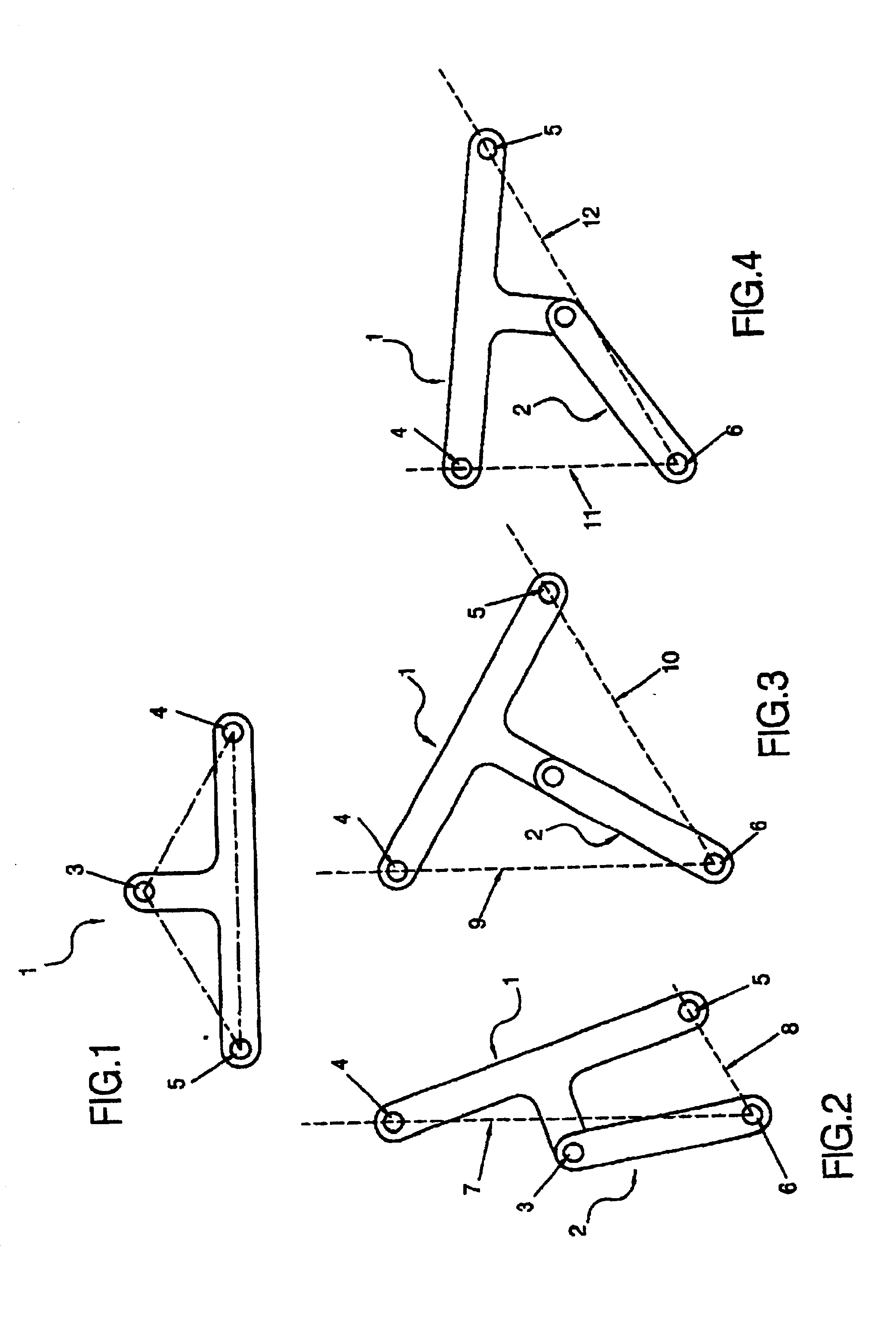
[0049]FIG. 1 shows a link 1 having three pivots 3, 4 and 5. Lines connecting these three pivots form an isosceles triangle 13, with pivots 4 and 5 lying on the base and pivot 3 at the apex.

[0050]FIG. 2 shows link 1 joined to link 2 by pivot 3. Link 2 has an additional pivot 6. Pivots 4, 5 and 6 are equidistant from pivot 3. A line 7 is drawn through pivots 4 and 6. A second line 8 is drawn through pivots 5 and 6.

[0051]In FIG. 3 links 1 and 2 are shown rotated about their common pivot 3 to a different relative position. A line 9 is drawn through pivots 4 and 6. A second line 10 is drawn through pivots 5 and 6. The angle formed between Lines 9 and 10 is identical to the angle formed between lines 7 and 8 as shown in FIG. 1.

[0052]In FIG. 4 links 1 and 2 are again shown in a different relative rotational position. The similarly drawn lines 11 and 12 again form an angle, which is identical to that formed in FIG. 1 and FIG. 2.

[0053]In general, given two joined links, the first having thre...


PUM


Abstract

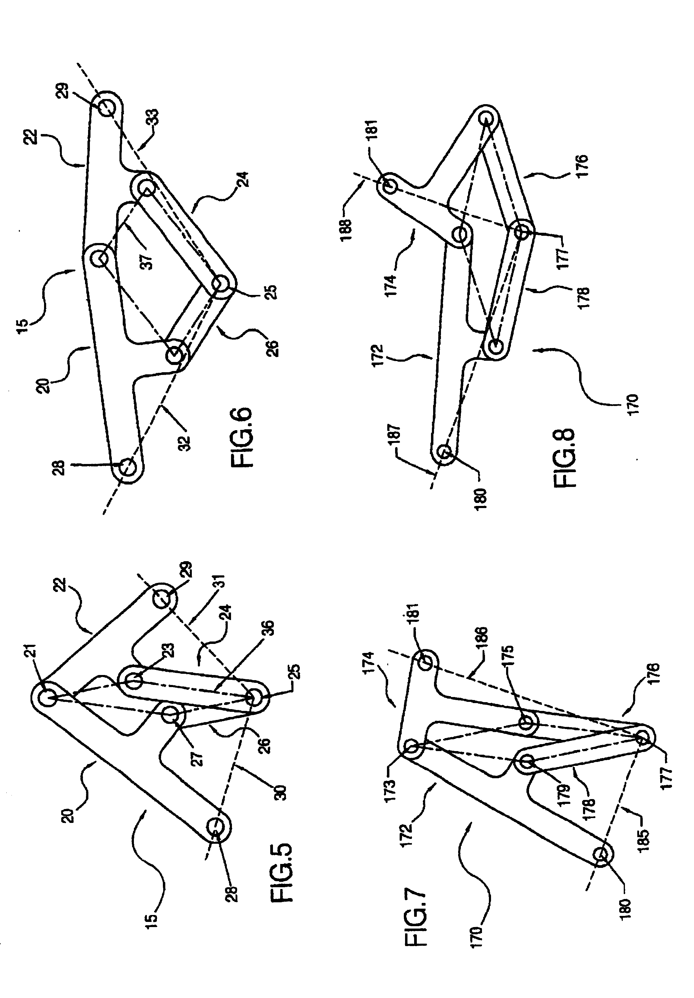
Improved reversibly expandable structures are formed from novel loop assemblies comprising a plurality of links, each of said links having at least one center pivot joint and a plurality of end pivot joints, each of at least two of said plurality of end pivot joints proximate to the outer edge of said loop assembly and connected to another link; each of said plurality of links being connected to another one of said plurality of links by at least two end pivot joints thereby forming a link pair, said loop assembly comprising at least three link pairs, each of said at least three link pairs connected to at least two other link pairs through at least one of said end pivot joints; each of said at least three link pairs connected to a central piece that is central to the loop assembly, said central piece being rotatable around a central axis, wherein the rotation of the central piece reversibly expands said loop assembly.

Description

REFERENCE TO RELATED APPLICATION[0001]This application claims the filing date of provisional patent application, Ser. No. 60 / 267,240, filed Feb. 7, 2001.BACKGROUND OF THE INVENTION[0002]U.S. Pat. Nos. 4,942,700, 5,024,031, 6,082,056 and 6,219,974, hereby incorporated by reference as if fully disclosed herein, teach methods for constructing reversibly expandable truss-structures in a wide variety of shapes. The teachings therein have been used to build structures for diverse applications including architectural uses, public exhibits and unique folding toys.[0003]Utilizing the teachings of these patents, self-supporting structures that maintain their overall shape as they expand or collapse in a synchronized manner may be constructed. A basic building block of such structures is a “loop-assembly” which consists of three or more scissor units (disclosed in the '700 and '031 patents) or polygon-link pairs (disclosed in the '056 and '974 patents), each consisting of a pair of links that ...

Claims


Application Information

Patent Timeline
IPC IPC(8): E04B7/08E04B1/32E04B1/344
CPCE04B1/3211E04B1/3441Y10S52/10E04B2001/3241
Inventor HOBERMAN, CHARLES
Owner HOBERMAN CHARLES
Learn More