
Method of producing membrane electrode assemblies for use in proton exchange membrane and direct methanol fuel cells

a technology of proton exchange membrane and fuel cell, which is applied in the direction of catalyst activation/preparation, metal/metal-oxide/metal-hydroxide catalyst, etc., can solve the problems of increasing the cost of cell components, cell performance and operating life, and the difficulty of producing commercially viable fuel cells, etc., to achieve the effect of improving performan

Inactive Publication Date: 2006-08-29
CABOT CORP
View PDF9 Cites 68 Cited by
  • Summary
  • Abstract
  • Description
  • Claims
  • Application Information

AI Technical Summary

Benefits of technology

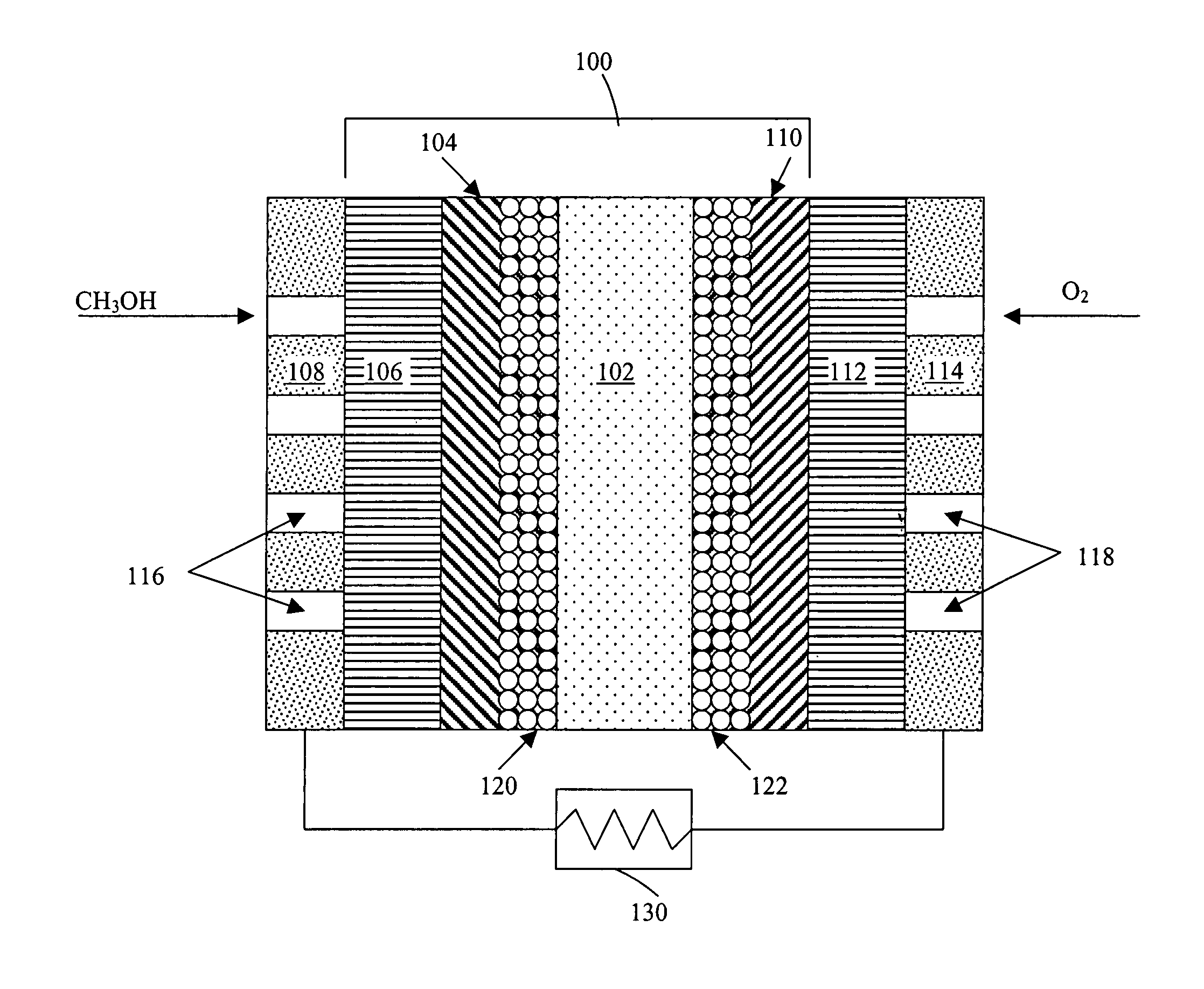
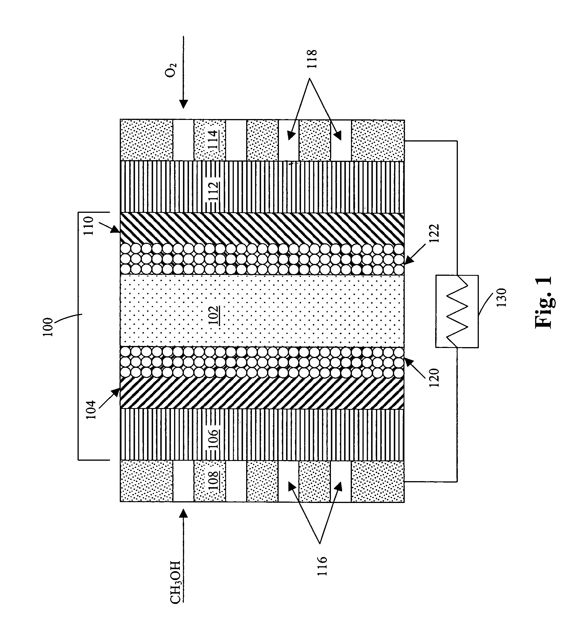
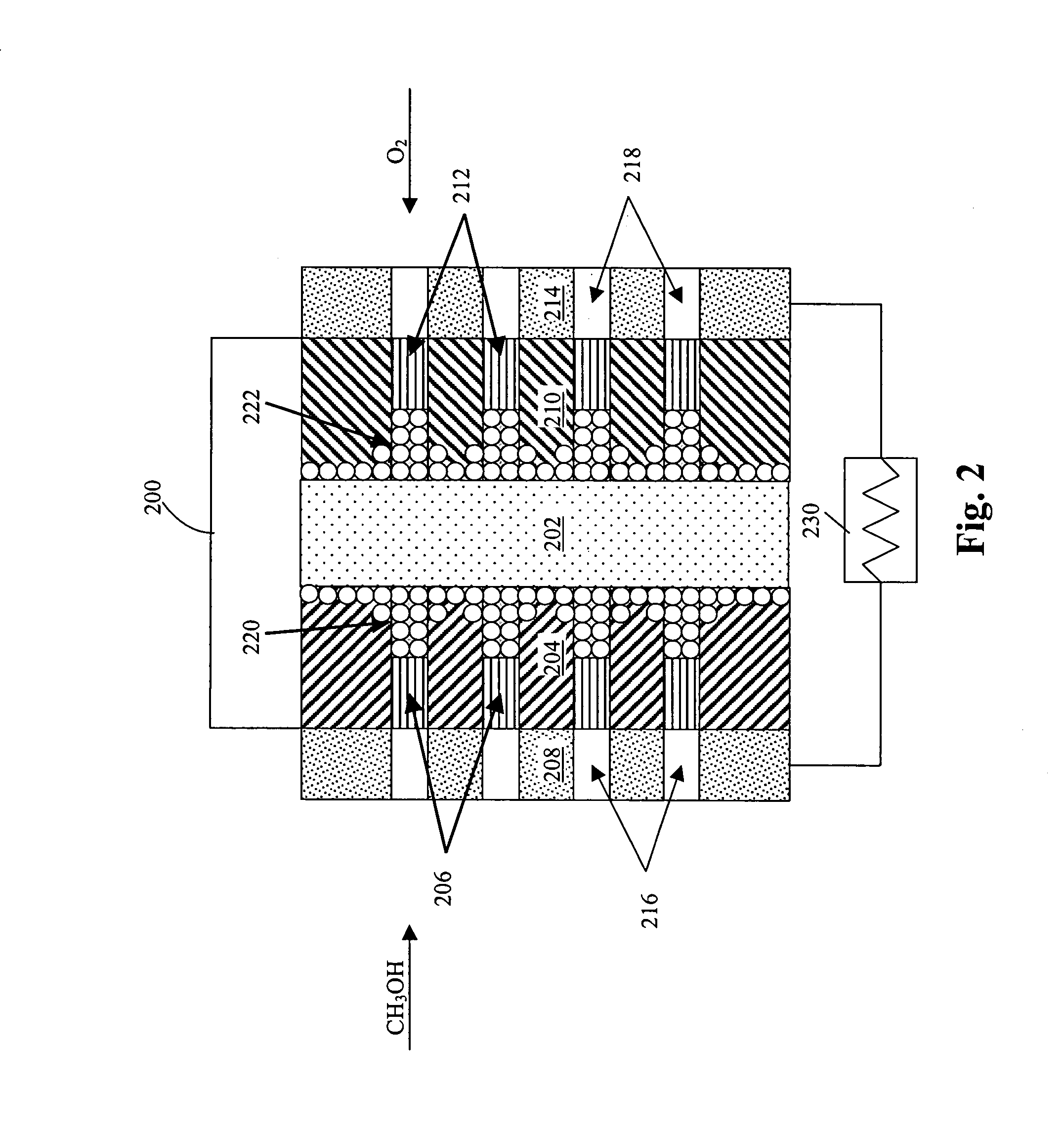
[0028]The present invention provides a method to manufacture MEAs for PEMFC and DMFC applications at high volumes with electrode structures that result in improved performance.
[0032]In a further aspect of the present invention, it is advantageous to use a direct write, preferably non-contact printing method to produce the gradient layer structures to enable the sequential coating of layers which can be printed / coated while the layers are still wet at one extreme, or substantially dry at the other extreme, to control the compositional gradient at the interface between the adjacent layers.

Problems solved by technology

Although the theory behind fuel cell operation has been known for over 100 years, there has been difficulty producing commercially viable fuel cells due to technological barriers, and also due to the availability of more cost-effective energy sources such as petroleum.
However, devices using petroleum products, such as the automobile, produce significant pollution and may eventually become obsolete with the depletion of petroleum resources.
Among the critical issues that must be addressed for the successful commercialization of fuel cells are cell cost, cell performance and operating lifetime.
A major technical challenge is enabling the efficient transport of methanol, water, oxygen, carbon dioxide, protons and electrons to and from the relevant locations in the MEA.
Most current manufacturing methods are not capable of forming structures that enable all around efficient transport of reactants and by-products within the MEA.
Most, conventional methods for manufacturing MEAs cannot deposit catalyst and other materials in predetermined locations to increase the catalyst utilization.
As a result, an unnecessarily large amount of catalyst is deposited.
However, there are many drawbacks to these manufacturing methods.
Many of the processes are laboratory methods, which cannot be used in full-scale manufacturing processes.
Many of the processes are slow and require significant amounts of down-time to change patterns.
Many of the processes cannot directly deposit materials on flexible or low-temperature surfaces such as thin polymer membranes.
Many of the processes cannot precisely control the volume or concentration of the deposited materials on selected microscopic areas of the substrate and many of the processes cannot deposit the materials on the substrate in a pattern or cannot deposit patterns with a small line width.
As a result, controlled gradients in composition, concentration or porosity within layers are difficult to fabricate.
Many of the processes are not compatible with all of the required materials which results in the use of different deposition methods during the fabrication of the MEA.
This increases the number of deposition steps, which in itself is inefficient and may lead to alignment errors within the MEA and lead to unnecessary handling and breakage of fragile components such as the thin PEM.
However, decal and lamination methods cannot produce fine patterns or gradients in composition without additional processing.
Moreover, aligning the various MEA layers can be difficult.

Method used


Image

  • Method of producing membrane electrode assemblies for use in proton exchange membrane and direct methanol fuel cells
  • Method of producing membrane electrode assemblies for use in proton exchange membrane and direct methanol fuel cells
  • Method of producing membrane electrode assemblies for use in proton exchange membrane and direct methanol fuel cells

Examples


examples

[0333]In the present specification, TEFLON (E.I. duPont de Nemours, Wilmington, Del.) refers to a hydrophobic polymer, more specifically a tetrafluoroethylene fluorocarbon polymer. NAFION (E.I. duPont de Nemours, Wilmington, Del.) refers to a hydrophobic and proton-conducting polymer, specifically a sulfurated perfluorohydrocarbon polymer.

[0334]The description and examples also make reference to various forms of carbon by reference to trade names. The general properties of these carbon supports are listed in Table 3. SHAWINIGAN BLACK is an acetylene black available from Chevron Chemical Co., Houston, Tex. KETJENBLACK is available from Akzo Nobel, Amersfoort, Netherlands. VULCAN XC-72 is a furnace black available from Cabot Corp., Alpharetta, Ga., and is also available in graphitized form. PWA is an activated carbon available from Calgon Carbon Corp., Pittsburgh, Pa.

[0335]

TABLE 3Carbon Blacks used as Catalyst SupportsParticle SizeCarbon Source(micrometers)BET Surface Area (m2 / g)SHAWI...

example

Graded Hydrophobicity Layers

[0390]A number of graded hydrophobicity layers were produced in accordance with the present invention. In a first example, a single layer of TEFLON-modified carbon was printed on top of an electrocatalyst layer, the other side of the electrocatalyst layer interfacing the electrolyte. The TEFLON-modified carbon layer consisted of 35 wt. % TEFLON and 65 wt. % SHAWINIGAN BLACK. The average thickness of the layer was 90 μm and the loading of the TEFLON-modified carbon was about 2.5 mg / cm2. The ink composition consisted of SHAWINIGAN BLACK, TEFLON particles, surfactants and water. The printed layer was then subjected to roll pressing and the sample was heated at 300° C. for 5 minutes to drive out surfactants used in the ink composition.

[0391]In a second example, two 50 μm thick sublayers of TEFLON-modified carbon were printed on top of an electrocatalyst layer, the other side of the electrocatalyst layer interfacing the electrolyte. The first sublayer of TEFLO...


PUM

PropertyMeasurementUnit
temperatureaaaaaaaaaa
viscosityaaaaaaaaaa
viscosityaaaaaaaaaa

Abstract

Compositions and methods for the manufacture of electrodes for fuel cells. The compositions and methods are particularly useful for the manufacture of anodes and cathodes for proton exchange membrane fuel cells, particularly direct methanol fuel cells. The methods can utilize direct-write tools to deposit ink compositions and form functional layers of a membrane electrode assembly having controlled properties and enhanced performance.

Description

CROSS-REFERENCE TO RELATED APPLICATIONS[0001]This application is a continuation-in-part of U.S. patent application Ser. No. 10 / 265,351 filed Oct. 4, 2002, which claims the benefit of U.S. Provisional Patent Application Ser. No. 60 / 327,620 filed Oct. 5, 2001, each of which is incorporated herein by reference in their entirety. This application is also a continuation-in-part of U.S. patent application Ser. No. 09 / 815,380, filed Mar. 22, 2001, which is a continuation-in-part of U.S. patent application Ser. No. 09 / 589,710, now U.S. Pat. No. 6,753,108, filed on Jun. 8, 2000, which is a continuation-in-part of U.S. patent application Ser. No. 09 / 532,917, now U.S. Pat. No. 6,660,680, filed on Mar. 22, 2000, which is a continuation-in-part of U.S. patent application Ser. No. 09 / 141,397, filed on Aug. 27, 1998, now U.S. Pat. No. 6,103,393. Each of these applications are incorporated herein by reference in their entirety.STATEMENT REGARDING FEDERALLY FUNDED RESEARCH[0002]This invention was ma...

Claims


Application Information

Patent Timeline
Patent Type & Authority Patents(United States)
IPC IPC(8): H01M4/88H01M4/86H01M4/90H01M4/96B01J20/28B01J21/18B01J23/00B01J23/34B01J23/40B01J31/06B01J35/00B01J37/00B01J37/34B22F9/02B22F9/30C09D11/00C22C29/00C22C32/00C23C18/06C23C18/08H01B1/02H01L21/288H01L21/314H01L21/316H01M4/92H01M8/10H01M12/08H05K1/03H05K1/09H05K1/16H05K3/10
CPCB01J21/18B01J23/34B01J23/40B01J35/023B01J35/10B01J37/0054B22F9/026B22F9/30B82Y30/00C09D11/101C09D11/30C22C29/00C22C32/0084C23C18/06C23C18/08H01B1/026H01L21/31691H01M4/8605H01M4/8636H01M4/881H01M4/8828H01M4/8832H01M4/8842H01M4/8882H01M4/90H01M4/9083H01M4/926H01M4/96H01M8/04261H01M8/1004H05K1/162H05K3/105B22F1/0048B01J23/00Y02E60/523B01J31/06B01J35/08B01J37/343B22F2998/00H01L21/288H01M4/9016H01M4/92H01M8/1009H01M12/08H01M2008/1095H05K1/0346H05K1/095H05K1/097H05K3/125H05K2203/013H05K2203/1142H01M8/04197Y02E60/50Y02P70/50H01L21/02197B01J35/31B01J35/30B01J35/33B01J35/40B01J35/51B22F1/065B22F1/08H01M4/88H01M4/86Y02E60/10
Inventor HAMPDEN-SMITH, MARK J.KODAS, TOIVO T.ATANASSOVA, PAOLINABHATIA, RIMPLEMIESEM, ROSS A.NAPOLITANO, PAULRICE, GORDON L.
Owner CABOT CORP
Learn More