
LED strobe light

a strobe light and led technology, applied in the field of strobe light, can solve the problems of high maintenance cost, high energy consumption of gas sources, and easy breakage of gas discharge strobe lamps, and achieve the effects of improving reliability, reducing energy consumption, and prolonging the life of strobe lamps

Active Publication Date: 2006-08-22
DIALIGHT CORP
View PDF7 Cites 40 Cited by
  • Summary
  • Abstract
  • Description
  • Claims
  • Application Information

AI Technical Summary

Benefits of technology

The present invention provides a new strobe light that uses an LED light source and has a unique driving circuit. This new strobe light has the benefits of being more energy-efficient, lasting longer, being more reliable, and having simpler supporting electronics compared to traditional gas discharge strobe lights.

Problems solved by technology

Incandescent light or gas sources have relatively high energy consumption and have relative short lifetimes, resulting in relatively high maintenance costs.
Gas discharge strobe lamps are also susceptible to breakage, produce intense ultraviolet light that breaks down many materials, and produce ozone due to high voltage requirements.
Such conventional gas discharge strobe lights also have reliability problems and have relatively complicated supporting electronics to maintain the flashing operation.

Method used


Image

  • LED strobe light
  • LED strobe light
  • LED strobe light

Examples


Embodiment Construction

[0010]In the drawings, like reference numerals designate identical or corresponding parts throughout the several views.

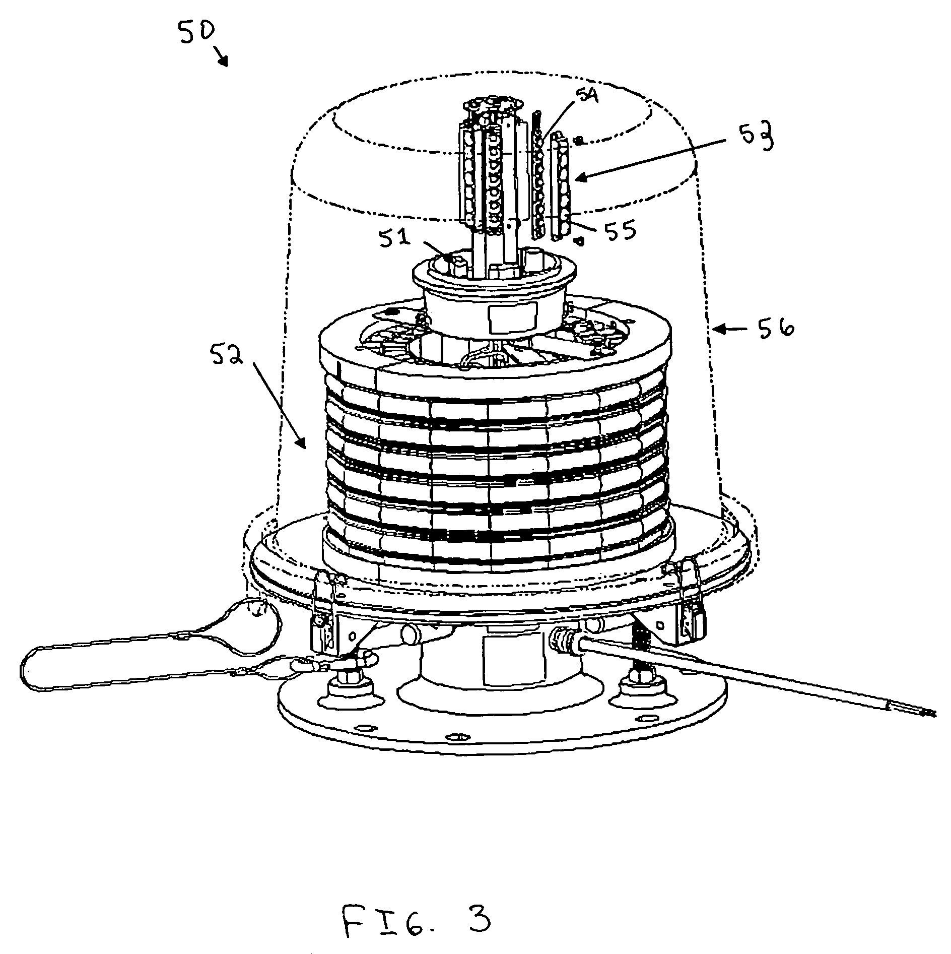
[0011]FIG. 1 shows an LED strobe light 10 of the present invention in an exploded view. As shown in FIG. 1, the LED strobe light 10 includes a main body portion 2 and a top reflector portion 1 to be positioned at a top of the main body portion 2. The top reflector portion 1 includes a conical-type shaped reflector reflecting light out of the main body portion 2.

[0012]FIG. 1 shows the LED strobe light 10 in which light is output radially from the top reflector portion 1. The specific embodiment shown in FIG. 1 is only one example of a structure that an LED strobe light can take. It is known in the art to utilize LED lights that output light in a unidirectional direction, and it is also known to use LED obstruction type lights to which the present invention can also be applied, as other examples.

[0013]Further, the main body portion 2 is placed on top of a driving cont...


PUM


Abstract

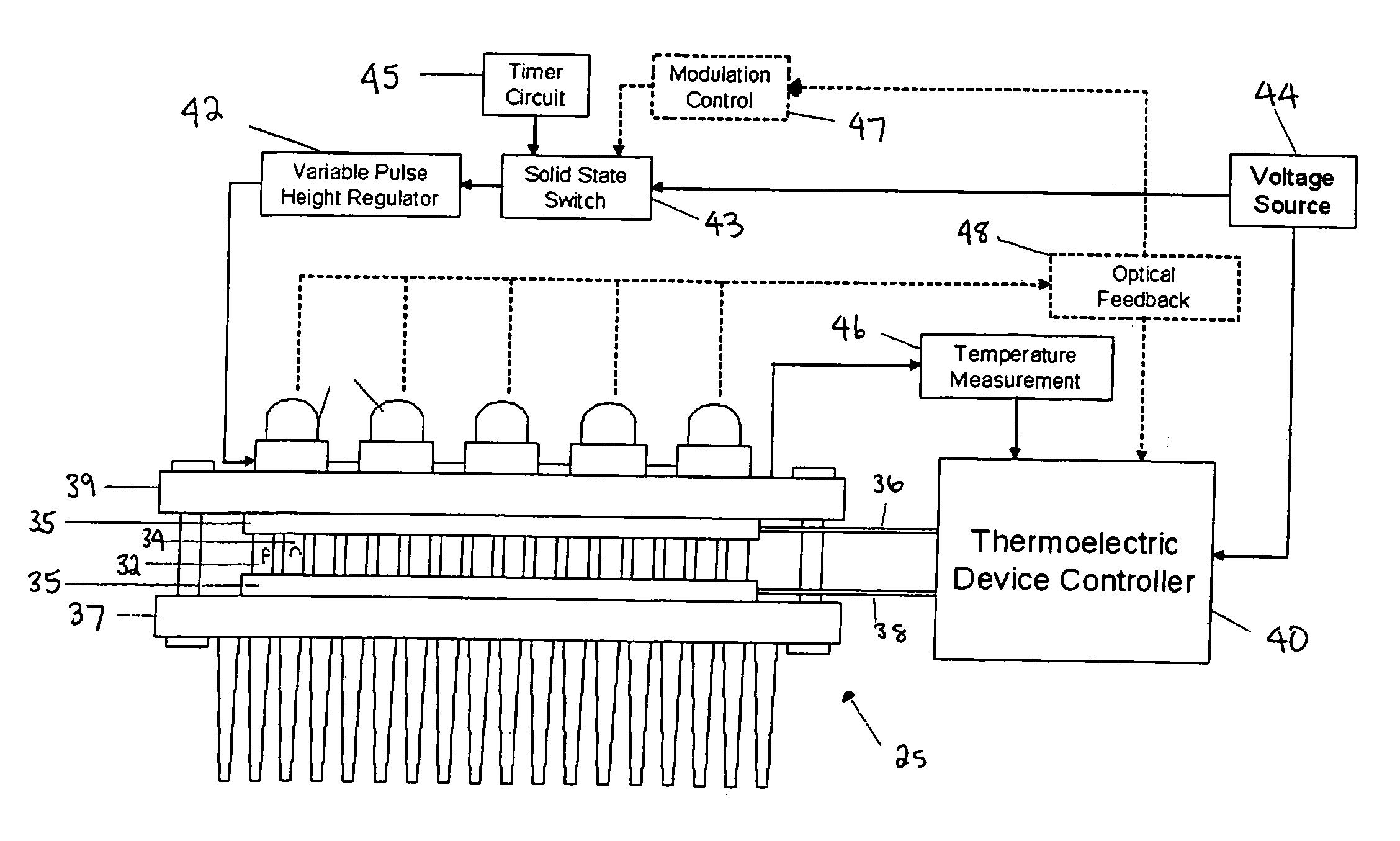
An LED light that includes an LED light source. A thermoelectric device is configured to maintain the LED light source within a predetermined temperature range. A controller provides a pulse signal to the LED light source, so that the LED light can particularly operate as a strobe light. Such an LED light can find application in an obstruction light.

Description

BACKGROUND OF THE INVENTION[0001]1. Field of the Invention[0002]The present invention is directed to a strobe light that includes a light emitting diode (LED) light source.[0003]2. Background of the Invention[0004]Gas discharge strobe lights are well known in the art. Such strobe lights find particular application for emergency vehicles, radio towers, photography, and entertainment venues. Such conventional strobe lights utilize incandescent or gas light sources, and most commonly are xenon discharge lamps. Incandescent light or gas sources have relatively high energy consumption and have relative short lifetimes, resulting in relatively high maintenance costs. Gas discharge strobe lamps are also susceptible to breakage, produce intense ultraviolet light that breaks down many materials, and produce ozone due to high voltage requirements. Such conventional gas discharge strobe lights also have reliability problems and have relatively complicated supporting electronics to maintain the...

Claims


Application Information

Patent Timeline
Patent Type & Authority Patents(United States)
IPC IPC(8): H05B37/02F21S8/00H01J13/32
CPCB60Q1/2611F21S48/328F21V23/0407F21V29/004F21V29/54H05B33/0803F21W2111/06F21Y2101/02Y10S362/80F21W2111/00F21Y2115/10F21V7/041F21V29/763H05B45/18H05B45/12F21S45/47H05B45/305H05B45/32H05B45/325
Inventor YOUNG, GARRETT J.
Owner DIALIGHT CORP
Learn More