Eureka AIR delivers breakthrough ideas for toughest innovation challenges, trusted by R&D personnel around the world.

System and method for efficiently implementing a battery controller for an electronic device

a battery controller and electronic device technology, applied in secondary cell servicing/maintenance, electrochemical generators, safety/protection circuits, etc., can solve the problems of increasing the requirements for power management functionality and performance, requiring more system processing power, and requiring additional hardware resources. , to achieve the effect of preventing overcharging the battery pack, and low on-state resistan

Active Publication Date: 2006-08-15
SONY CORP +1
View PDF13 Cites 17 Cited by
  • Summary
  • Abstract
  • Description
  • Claims
  • Application Information

AI Technical Summary

Benefits of technology

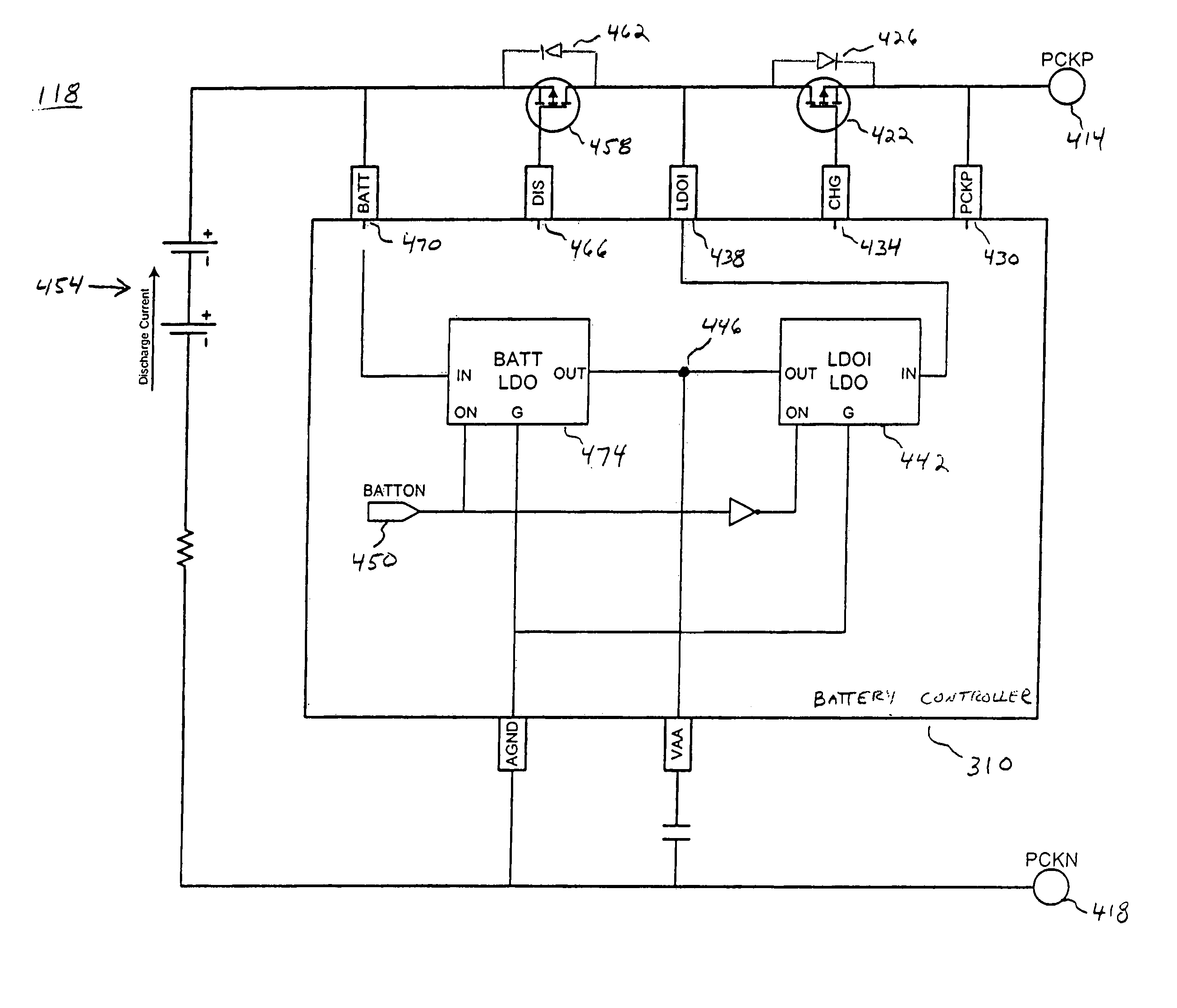
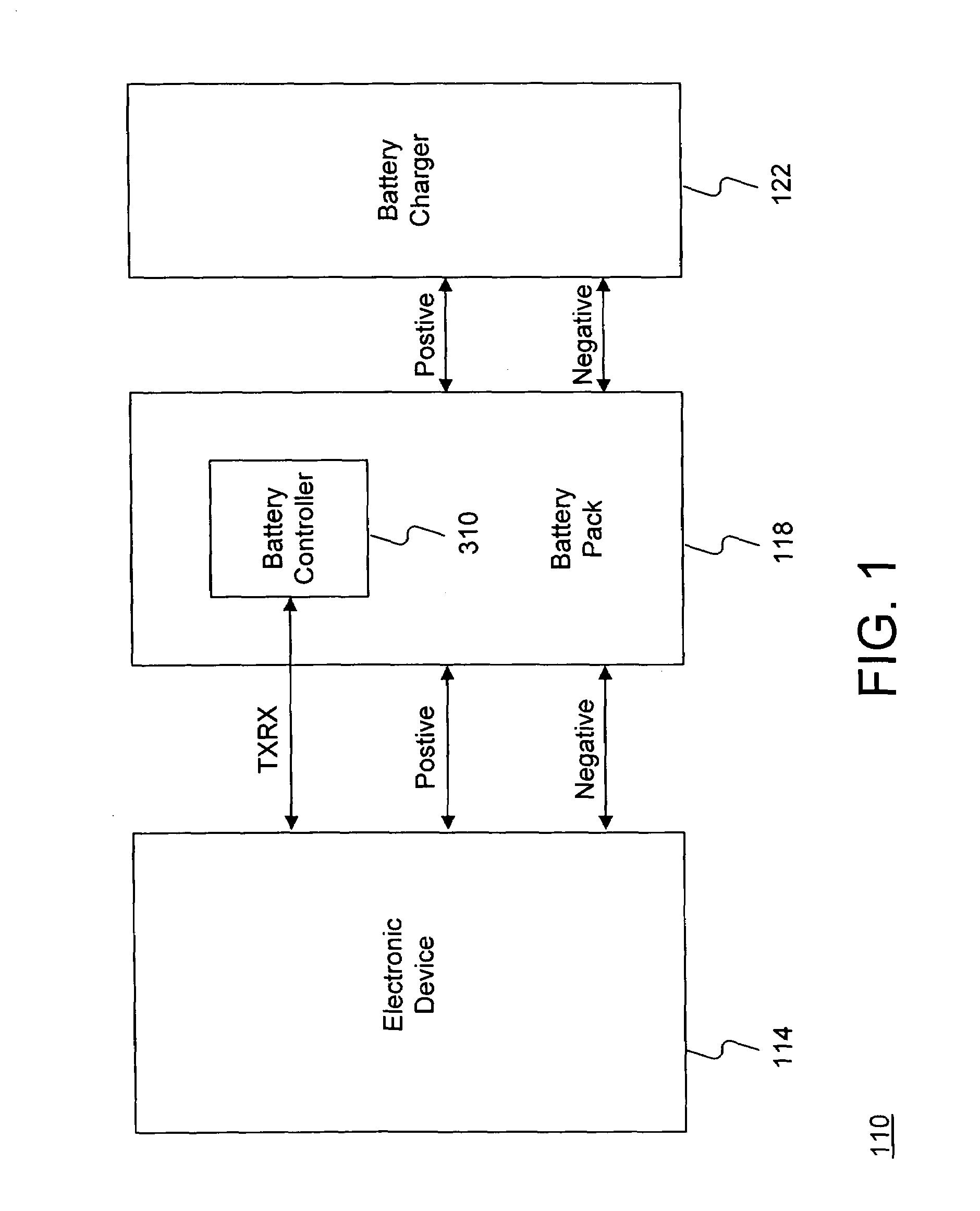
[0008]In accordance with the present invention, a system and method for effectively implementing a battery controller for an electronic device are disclosed. In one embodiment, the battery controller may be implemented as a single-chip integrated circuit device that controls various functionalities of a battery pack for effectively providing operating power to the electronic device. In accordance with certain embodiments of the present invention, the battery controller may be selectively configured to control the battery pack in either a single-cell implementation or a dual-cell implementation.
[0009]In a single-cell implementation in which the battery pack provides a reduced battery supply voltage, the battery controller may utilize a charge pump to convert the battery supply voltage into a sufficient internal controller power supply for operating the battery controller. The battery controller may thus effectively utilize the foregoing charge pump to compensate for the reduced battery supply voltage resulting from a single-cell implementation of the battery pack.
[0010]Under certain conditions, the battery controller may open a discharge switch to prevent overdischarging the battery pack. In addition, the battery controller may also open a charge switch to prevent overcharging the battery pack under other conditions. In certain embodiments, the battery controller may utilize an internal negative charge pump to provide a negative charge-pump output voltage for generating an enhancement voltage so that the charge switch and the discharge switch may exhibit sufficiently low on-state resistances when turned on.
[0011]Certain embodiments of the battery controller may also include a UART device to perform various bi-directional communications between the battery controller and appropriate external entities such as a processor of the corresponding electronic device. The UART device may be advantageously implemented to communicate with the electronic device via a single transmit / receive pin on the integrated circuit device that contains the battery controller. In addition, the UART device may advantageously receive a timebase signal from a precision on-chip instruction oscillator of the battery controller for accurately generating a UART clock signal to synchronize operations in the UART device. For at least the foregoing reasons, the present invention thus provides an improved system and method for effectively implementing a battery controller for an electronic device.

Problems solved by technology

However, effectively managing operating power for electronic devices may create substantial challenges for system designers.
For example, enhanced demands for increased power management functionality and performance may require more system processing power and require additional hardware resources.
An increase in processing or hardware requirements may also result in a corresponding detrimental economic impact due to increased production costs and operational inefficiencies.
In certain operational environments that involve portable electronics devices, knowing in advance when a given battery pack will become fully-discharged is an issue of some importance to a device user.
For example, when using a digital camera device to capture image data, failure to provide sufficient operating power to the digital camera device may temporarily prevent capture of additional image data at a critical point in time.

Method used


Image

  • System and method for efficiently implementing a battery controller for an electronic device
  • System and method for efficiently implementing a battery controller for an electronic device
  • System and method for efficiently implementing a battery controller for an electronic device

Examples


Embodiment Construction

[0019]The present invention relates to an improvement in power management techniques. The following description is presented to enable one of ordinary skill in the art to make and use the invention and is provided in the context of a patent application and its requirements. Various modifications to the disclosed embodiments will be readily apparent to those skilled in the art, and the generic principles herein may be applied to other embodiments. Thus, the present invention is not intended to be limited to the embodiments shown, but is to be accorded the widest scope consistent with the principles and features described herein.

[0020]The present invention comprises a system and method for effectively managing operating power for an electronic device, and may include a battery pack coupled to the electronic device for supplying operating power to the electronic device. A battery controller may be configured as a single integrated-circuit device to alternately manage the battery pack e...


PUM

PropertyMeasurementUnit
total voltageaaaaaaaaaa
voltageaaaaaaaaaa

Abstract

A system and method for effectively managing operating power for an electronic device may include a battery pack coupled to the electronic device for supplying operating power to the electronic device. A battery controller may be configured as a single integrated-circuit device to alternately manage the battery pack either in a single-cell implementation or in a dual-cell implementation. The battery controller may include a charge pump device to provide an internal controller power supply for operating the battery controller in the single-cell implementation.

Description

BACKGROUND SECTION[0001]1. Field of the Invention[0002]This invention relates generally to techniques for managing operating power of electronic devices, and relates more particularly to a system and method for effectively implementing a battery controller for an electronic device.[0003]2. Description of the Background Art[0004]Implementing efficient methods for managing operating power is a significant consideration for designers and manufacturers of contemporary electronic devices. However, effectively managing operating power for electronic devices may create substantial challenges for system designers. For example, enhanced demands for increased power management functionality and performance may require more system processing power and require additional hardware resources. An increase in processing or hardware requirements may also result in a corresponding detrimental economic impact due to increased production costs and operational inefficiencies.[0005]Furthermore, enhanced s...

Claims


Application Information

Patent Timeline
Patent Type & Authority Patents(United States)
IPC IPC(8): H02J7/00H02J7/06H02J7/16H02J7/24H01MH01M10/42H01M10/44
CPCH01M10/42H01M10/425H01M10/441H02J7/0031H02M3/07H02J2007/0067H02J2007/0095H02J2207/10Y02E60/10H02J7/007182H02J7/00712
Inventor MADER, URS H.SATO, HIDEYUKI
Owner SONY CORP
Why Eureka
Eureka Blog
Learn More