
LDPC encoding methods and apparatus

a technology of encoding methods and encoding apparatus, applied in the direction of coding, code conversion, electrical apparatus, etc., can solve the problems of encoding memory going unused, memory locations, block storage locations, etc., and achieve the effect of simple microcod

Active Publication Date: 2006-01-26
QUALCOMM INC
View PDF43 Cites 160 Cited by
  • Summary
  • Abstract
  • Description
  • Claims
  • Application Information

AI Technical Summary

Benefits of technology

[0014] The present invention is directed to encoding methods and apparatus, e.g., methods and apparatus for implementing a low density parity check (LDPC) encoder. Various embodiments of the invention are directed to particularly flexible encoders which allow a single encoder to be used to encode codewords of different lengths. This allows an LDPC encoder of the present invention to switch between encoding codewords of a first length for a first application, e.g., a first communications application or data storage application, to encoding codewords of a second length for a second application. In fact, a wide variety of codeword lengths can be supported using the same hardware allowing for changes in codeword length through simple modifications in the codeword description used in the encoder. Codeword descriptions may be reflected in relatively simple microcode which can be executed as needed for a particular application.
[0016] The encoder of the present invention can switch between different lifting factors thereby allowing the encoder to switch between generating codewords of different lengths. Thus, the encoder of the present invention can be used to generate codewords of a length which is well suited for a particular application and is not constrained by hardware to generating codewords of a single length. However, the maximum supported codeword length in many cases will be a function of the amount of memory available for storing blocks of bits during encoding.
[0021] We may restrict the permutations to be in the space of a set (usually a group) of Z×Z permutation matrices, denoted as Ψ. Thus, Ψ will be used herein to refer to a set of permuation matrices which is usually a group of permuation matrixes. We assume that the inverses of the permutations in Ψ are also in Ψ. The set Ψ can in general be chosen using various criteria. One of the main motivations for the above structure is to simplify hardware implementation of decoders and encoders. Therefore, it can be beneficial to restrict Ψ to permutations that can be efficiently implemented in hardware, e.g., in a switching network.
[0028] The size of the microcode used in accordance with the invention to describe the lifted graph is thus roughly equal to the number of edges in the projected graph plus the number of additional commands specifying the inversion, which is often small. Therefore, for identical block length, increasing the lifting factor generally reduces the size of the encoding microcode. For large block length, this may save significantly in microcode description memory, e.g., a relatively small memory may be used to store the information describing the large graph to be used for encoding.
[0032] Given the fact that hardware complexity is proportional to the implementation parallelism N but graph description complexity is proportional to the lifting factor Z, it is desirable that the implementation parallelism is such that the resulting throughput is matching the requirement without excessiveness while using a lifted graph described using a large lifting factor Z.

Problems solved by technology

Use of a code lifting factor less than the maximum supported code lifting factor will normally result in some memory locations, e.g., block storage locations, going unused in the encoder memory.

Method used


Image

  • LDPC encoding methods and apparatus
  • LDPC encoding methods and apparatus
  • LDPC encoding methods and apparatus

Examples


Embodiment Construction

[0041] The present invention is directed to methods and apparatus for implementing LDPC encoders. Various embodiments of the invention are directed to LDPC encoders and encoding methods which can be implemented in a hardware efficient manner while being relatively flexible with regard to the code structure that can be used during encoding and the size of generated codewords.

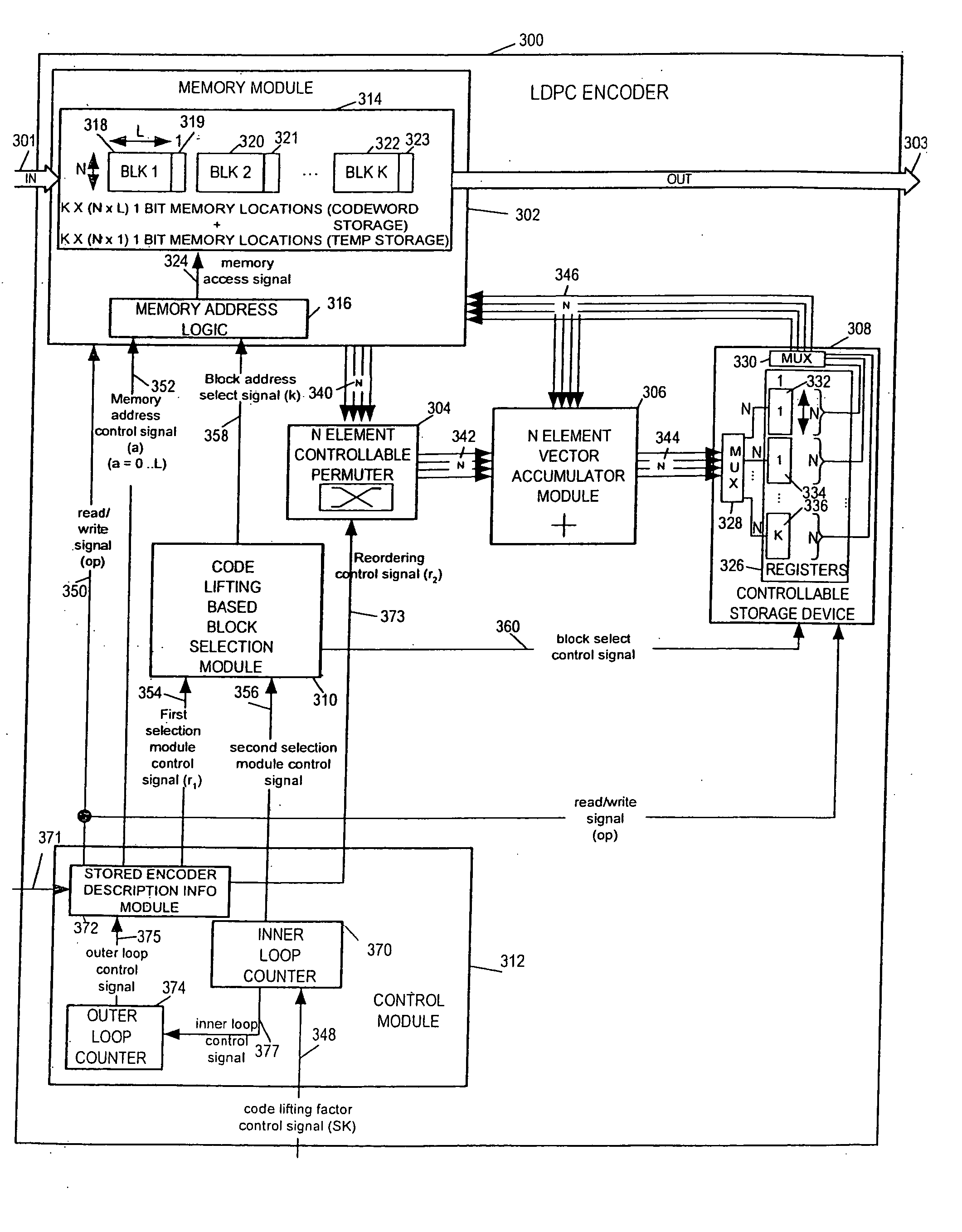
[0042]FIG. 3 illustrates an exemplary LDPC encoder 300 implemented in accordance with the present invention. The encoder includes a memory module 302, a control module 312, a code lifting based block selection module 310, an N element controllable permuter 304, an N element vector accumulator module 306 and a controllable storage device 308 which are coupled together as shown in FIG. 3. Note that the terms permuter and permutator are used interchangeable in the present application to refer to the same thing. The various elements of the LDPC encoder 300 and their function will be described in detail below.

[0043]...


PUM


Abstract

A flexible and relatively hardware efficient LDPC encoder is described. The encoder can be implemented with a level of parallelism which is less than the full parallelism of the code structure used to control the encoding process. Each command of a relatively simple microcode used to describe the code structure can be stored and executed multiple times to complete the encoding of a codeword. Different codeword lengths can be supported using the same set of microcode instructions but with the code being implemented a different number of times depending on the lifting factor selected to be used. The LDPC encoder can switch between encoding codewords of different lengths, without the need to change the stored code description information, by simply changing a code lifting factor used to control the encoding processes. When coding codewords shorter than the maximum supported codeword length some block storage locations and / or registers may go unused.

Description

FIELD OF THE INVENTION [0001] The present invention is directed to methods and apparatus for encoding data for the purposes of facilitating the detection and / or correction of errors, e.g., through the use of parity check codes such as low-density parity-check (LDPC) codes. BACKGROUND [0002] Error correcting codes are ubiquitous in communications and data storage systems. Error correcting codes compensate for the intrinsic unreliability of information transfer in these systems by introducing redundancy into the data stream. Recently considerable interest has grown in a class of codes known as low-density parity-check (LDPC) codes. LDPC codes are provably good codes. On various channels, LDPC codes have been demonstrated to be really close to the channel capacity—the upper limit for transmission established by Claude Shannon. [0003] LDPC codes are often represented by bipartite graphs, called Tanner graphs, in which one set of nodes, the variable nodes, correspond to bits of the codew...

Claims


Application Information

Patent Timeline
Patent Type & Authority Applications(United States)
IPC IPC(8): H03M13/00
CPCH03M13/116H03M13/611H03M13/6508H03M13/118H03M13/11H03M13/00
Inventor RICHARDSON, TOMJIN, HUI
Owner QUALCOMM INC
Learn More