
Color OLED device having improved performance

a technology of color display and oled, which is applied in the direction of solid-state devices, electric lighting sources, electric light sources, etc., can solve the problems of requiring significantly more manufacturing steps, and not being able to match the peak of the spectral transmission function of the color filter, so as to improve the power efficiency and display life without reducing the luminance of the display. , the effect of expanding the color gamu

Active Publication Date: 2006-08-15
GLOBAL OLED TECH
View PDF9 Cites 114 Cited by
  • Summary
  • Abstract
  • Description
  • Claims
  • Application Information

AI Technical Summary

Benefits of technology

"The patent describes a color OLED device with multiple pixels, each containing multiple layers of electroluminescent organic material that produce light with a variable frequency-dependent luminous efficacy emission spectrum. The device also includes filters to emit different colors of light. The device can emit at least two different colors of light that match the first color gamut of the device, and at least one additional color that matches a portion of the broadband light frequency range with higher radiant intensity. The additional color emitting elements have higher luminous efficiency than the three light-emitting elements that match the first color gamut. The invention allows for improved power efficiency and display lifetime without decreasing the luminance of the display, and can also expand the color gamut."

Problems solved by technology

However, the known red and blue emissive materials are not particularly power efficient.
However, these devices require significantly more manufacturing steps than would be required if a white material can be formed by doping only two emissive layers as each doped emission layer is typically formed by applying multiple coating steps, including a host, dopant, an optional co-dopant and an optional connecting layer.
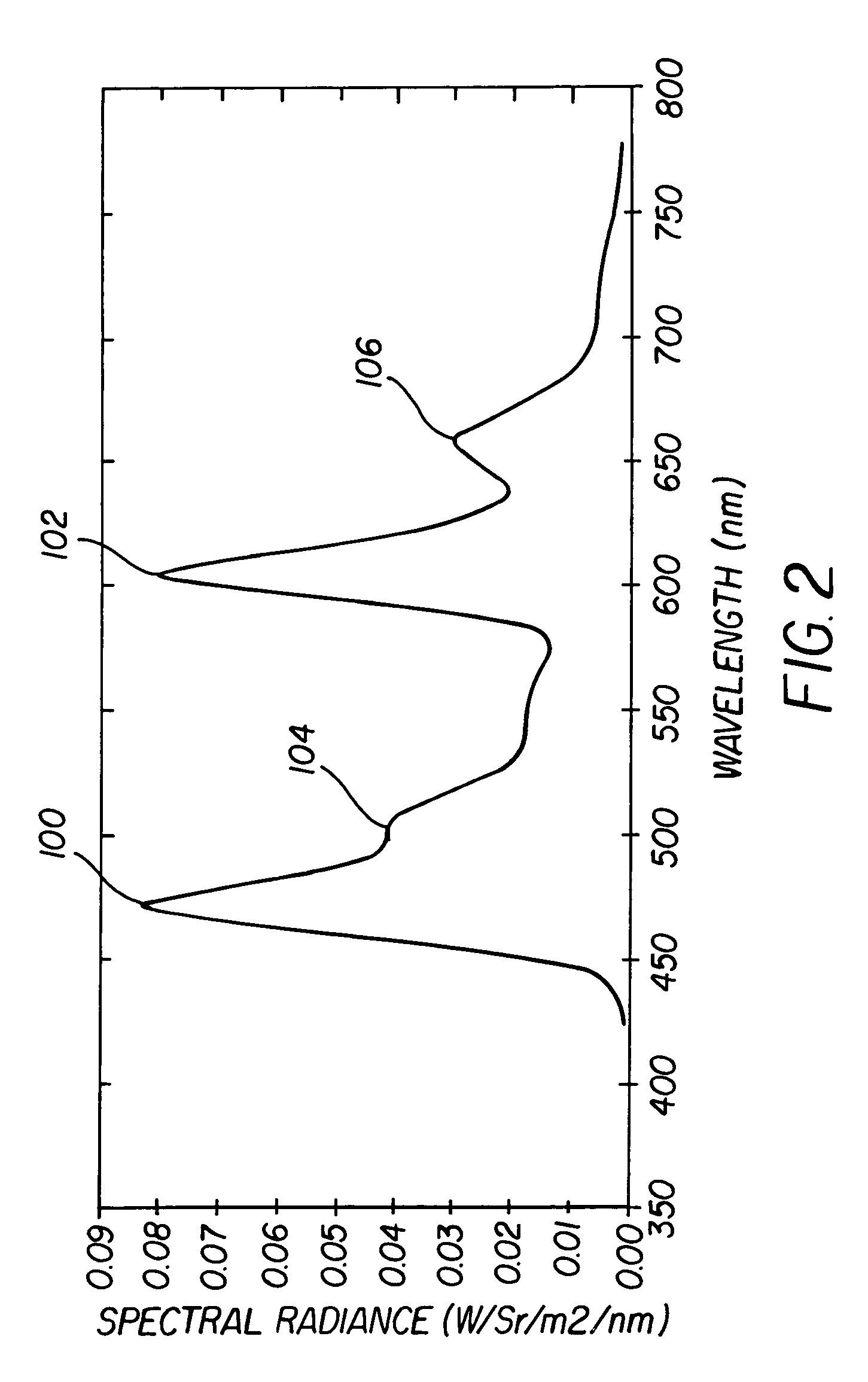
Unfortunately, in these devices, the peak in the spectral energy distribution for the cyan or yellow light emitting layers can not be matched to the peak in the spectral transmission function for the color filters.
For this reason, much of the energy emitted by the device is absorbed by the color filters rather than being transmitted to the observer, resulting in a display device with lower energy efficiency, particularly when narrow-band color filters are employed in order to create a display device with good color saturation and a large color gamut volume.
Unfortunately, increasing the current density used to drive an OLED not only increases the power required to drive the OLED but also reduces the lifetime of the OLED since the lifetime of an OLED emitter, as is known in the prior art, depends on the total current driven through the OLED emitter.
Therefore, increasing the luminance of an OLED display not only increases the power needed to drive the OLED display device but can significantly reduce the lifetime of the OLED display device.
Similarly, to increase the color gamut, the peak wavelength of the red light emitting element must be increased, producing energy that is even longer in wavelength and further reducing the eye's sensitivity to the radiant energy provided by the light emitting element.
Since the red and blue light emitting elements typically have relatively low luminance efficiency, as discussed earlier, the power consumption of the display device will be near its maximum when displaying white or a desaturated color.
However, neither of these references discuss OLED display devices that are constructed from white materials with color filters to create light emission for either color, nor do they discuss any reason why the radiant efficiency of the materials used to create a cyan light emitting element may be higher than the radiant efficiency of the materials used to create a blue light emitting element.

Method used


Image

  • Color OLED device having improved performance
  • Color OLED device having improved performance
  • Color OLED device having improved performance

Examples


Embodiment Construction

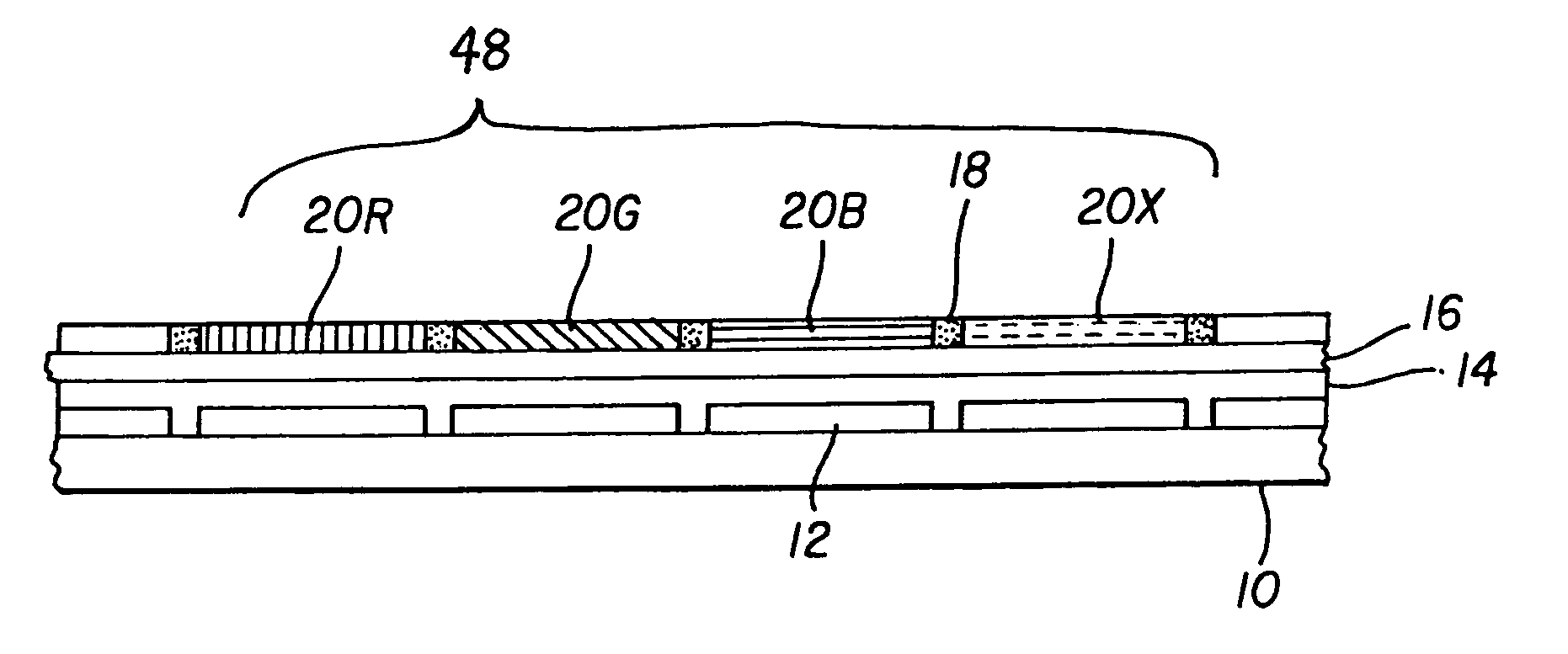
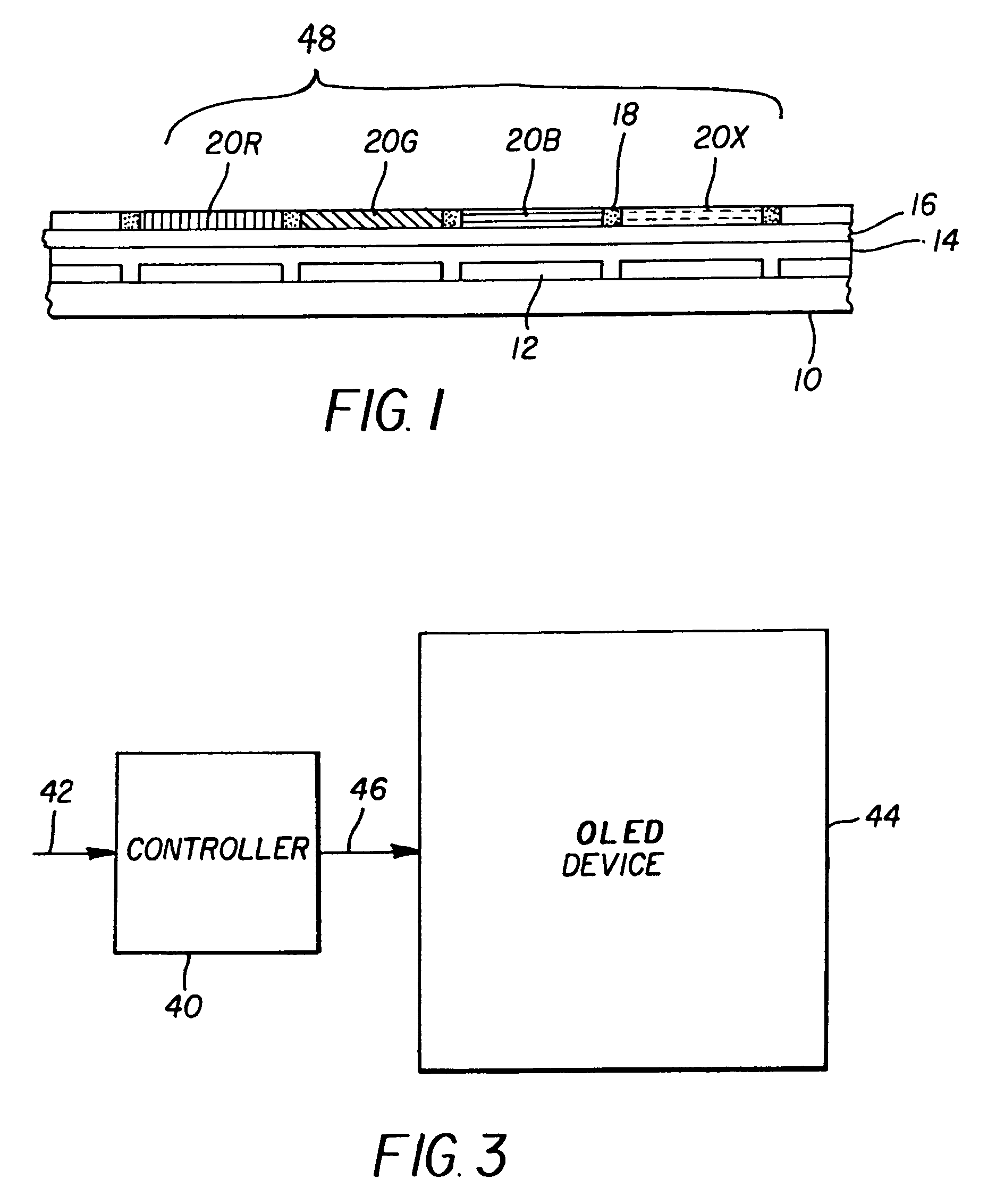
[0020]The present invention is directed to a color OLED device having one or more pixels, at least one pixel comprising four or more light-emitting elements, each light-emitting element comprising one or more layers of electroluminescent organic material producing a broadband light having a variable frequency-dependent luminous efficacy emission spectrum, and each light-emitting element further comprising a filter for filtering the broadband light and emitting a different color of light. As is known, luminous efficacy of a light source is dependent upon the radiant emission of the light source in combination with the response sensitivity of the human visual system. In the present invention, the different colors of light emitted by three of the light-emitting elements specify a first color gamut of the OLED device, and an additional one or more of the light-emitting elements emit at least one additional different color of light, and the frequency range of the filter of the additional...


PUM


Abstract

A color OLED device is described having one or more pixels, at least one pixel comprising: four or more light-emitting elements, each light-emitting element comprising one or more layers of electroluminescent organic material producing a broadband light having a variable frequency-dependent luminous efficacy emission spectrum, and each light-emitting element further comprising a filter for filtering the broadband light and emitting a different color of light; wherein the different colors of light emitted by three of the light-emitting elements specify a first color gamut of the OLED device, and an additional one or more of the light-emitting elements emit at least one additional different color of light and wherein the frequency range of the filter of the additional light emitting element is matched to a portion of the broadband light frequency range having a radiant intensity greater than the radiant intensity of the frequency range of at least one of the filters of the three light-emitting elements specifying the first color gamut of the OLED device, and the additional one or more light emitting elements having luminous efficiency greater than that of at least one of the three light emitting elements specifying the first color gamut.

Description

FIELD OF THE INVENTION[0001]The present invention relates to organic light emitting diode (OLED), full color display devices and, more particularly, to OLED color displays with improved gamut, power efficiency, and lifetime.BACKGROUND OF THE INVENTION[0002]Color, digital image display devices are well known and are based upon a variety of technologies such as cathode ray tubes, liquid crystal and solid-state light emitters such as Organic Light Emitting Diodes (OLEDs). In a common OLED color display device a pixel includes red, green, and blue colored OLEDs. By combining the illumination from each of these three OLEDs in an additive color system, a full-color display having a wide variety of colors can be achieved.[0003]OLEDs may be used to generate color directly using organic materials that are doped to emit energy in desired portions of the electromagnetic spectrum. However, the known red and blue emissive materials are not particularly power efficient. In fact, broad bandwidth (...

Claims


Application Information

Patent Timeline
Patent Type & Authority Patents(United States)
IPC IPC(8): H01L27/15H01L27/32
CPCH01L27/322H01L27/3213H10K59/351H10K59/38H05B33/02H05B33/22
Inventor COK, RONALD S.MILLER, MICHAEL E.
Owner GLOBAL OLED TECH
Learn More