Display device, display method, and projector
a technology of display method and display device, which is applied in the direction of picture reproducers using projection devices, identification means, instruments, etc., can solve the problems of inevitably increasing manufacturing cost, large size of color separation system or illumination system, such as light source, and needing to be large, so as to achieve excellent imaging performance, substantially enlarged color gamut, and excellent image quality
- Summary
- Abstract
- Description
- Claims
- Application Information
AI Technical Summary
Benefits of technology
Problems solved by technology
Method used
Image
Examples
first embodiment
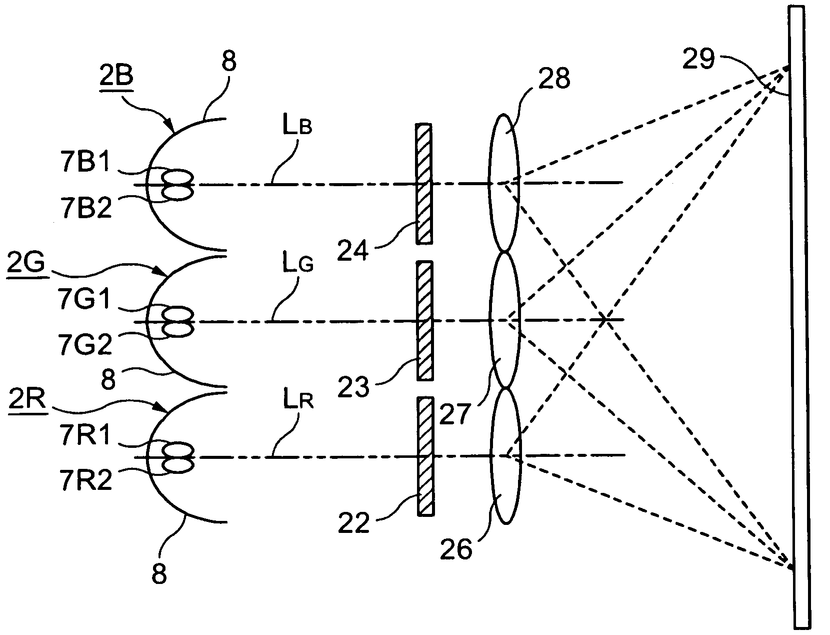
[0057]FIG. 1 schematically illustrates the structure of a projection display device according to the invention. The projection display device of FIG. 1 includes an illumination system (illumination means) having light sources 2R, 2G, and 2B capable of emitting primary color light having different emitted colors, liquid crystal light valves (light modulation device) 22 to 24, and projection devices 26 to 28. Reference numeral 29 denotes a screen onto which an image is projected.
[0058]The light source 2R for emitting red light (primary color light) LR includes two light-emitting devices 7R1 and 7R2 and a reflector 8 for reflecting light of the light-emitting devices 7R1 and 7R2. The light source 2G for emitting green light (primary color light) LG includes two light-emitting devices 7G1 and 7G2 and a reflector 8 for reflecting light of the light-emitting devices 7G1 and 7G2. The light source 2B for emitting blue light (primary color light) LB includes two light-emitting devices 7B1 an...
third embodiment
[0096]FIG. 13 schematically illustrates a liquid crystal display device according to the invention. The liquid crystal display device of FIG. 13 includes an illumination system (illumination device) 130 having a plurality of light-emitting devices, a light guide panel 131, a color filter 133 disposed on the front face of the light guide panel 131, and a liquid crystal panel 135 disposed on the front face of the color filter 133.
[0097]The illumination system 130 can include a pair of light-emitting devices 17R consisting of light-emitting devices 7R1 and 7R2 for emitting red light, a pair of light-emitting devices 17G consisting of light-emitting devices 7G1 and 7G2 for emitting green light, and a pair of light-emitting devices 17B consisting of light-emitting devices 7B1 and 7B2 for emitting blue light. In other words, the pairs of light-emitting devices 17R, 17G, and 17B are used as elements corresponding to the light sources in the first embodiment so that primary color light emit...
fourth embodiment
[0101]FIG. 16 schematically illustrates the structure of a projection display device according to the invention. The projection display device of FIG. 16 can include an illumination system (illumination device) having light sources 2R, 2G, and 2B, liquid crystal light valves 22 to 24 provided to correspond to each light source, a dichroic prism 15 for composition of light output from the liquid crystal light valves 22 to 24 and generating a displayed image, and a projection device 16. In addition, in FIG. 16, the same elements as those of FIG. 1 are given the same reference numerals, and detailed description thereof will be appropriately omitted.
[0102]The projection display device according to the embodiment can have the same structure as that of the projection display device according to the first embodiment, except that a dichroic prism 15, which is a color composite device, is provided and an image is projected from a single projection device 16. However, the projection display d...
PUM
 Abstract
Description
Claims
Application Information
 - R&D
- Intellectual Property
- Life Sciences
- Materials
- Tech Scout
- Unparalleled Data Quality
- Higher Quality Content
- 60% Fewer Hallucinations
Browse by: Latest US Patents, China's latest patents, Technical Efficacy Thesaurus, Application Domain, Technology Topic, Popular Technical Reports.
© 2025 PatSnap. All rights reserved.Legal|Privacy policy|Modern Slavery Act Transparency Statement|Sitemap|About US| Contact US: help@patsnap.com


