
Method for optimizing utilization of a double-data-rate-SDRAM memory system

Active Publication Date: 2006-08-08
ORACLE INT CORP
View PDF2 Cites 90 Cited by
  • Summary
  • Abstract
  • Description
  • Claims
  • Application Information

AI Technical Summary

Benefits of technology

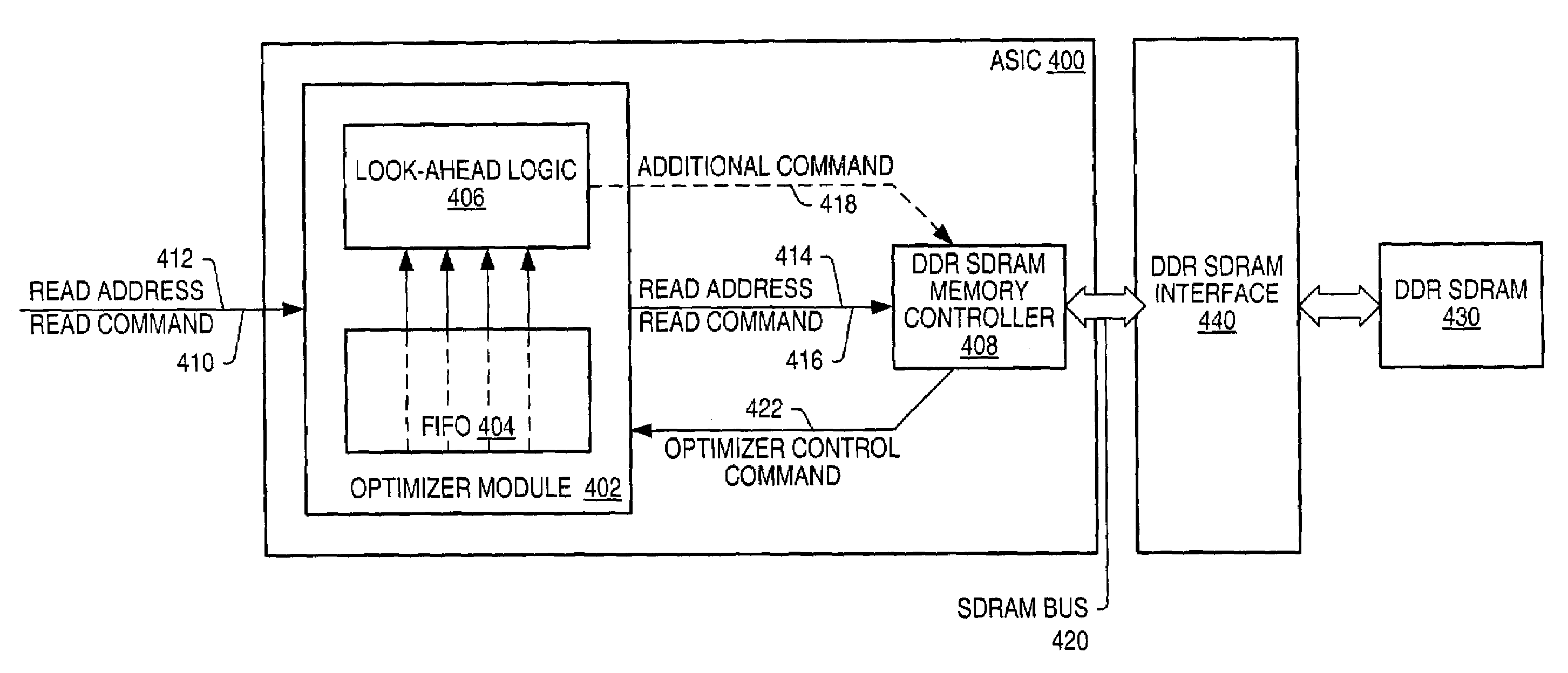
[0012]Thus, various embodiments of the invention may provide a means for optimizing an DDR SDRAM memory system containing interleaved DDR SDRAM memory devices through the employment of an optimizer module comprising a FIFO buffer and a look-ahead logic circuit. In one embodiment, the method includes maintaining a list of pending read-requests for data from the memory in the FIFO buffer. Pending read-requests may arrive to the FIFO buffer every other clock cycle, with an idle clock cycle following a cycle in which a pending read-request was received by the FIFO buffer. The look-ahead logic circuit may execute a look-ahead algorithm during an idle cycle. The look-ahead algorithm may select and transmit an additional memory command to the memory controller. The additional memory command may be an entry retrieved from a lookup table based on an examination of all pending read-requests residing in the FIFO buffer and the state of the memory banks. In one embodiment, the transmitting of the additional memory command results in a reduced number of clock cycles required by the memory controller to collectively handle all pending read-requests it receives from the FIFO buffer.

Problems solved by technology

This consistent increase in data and data rates places additional burden on the memory systems that form an integral part of the graphics system.
Thus, poor performance of the texture buffer is capable of affecting a cascading degradation through the graphics system, stalling the render pipeline, and increasing the render or refresh times of displayed images.
However, factors inherent in DRAM devices, and bus protocols, such as pre-charge time, activation time, refresh period, and others may complicate integration into high bandwidth applications such as high performance graphics systems.
DDR SDRAM systems increase the throughput of DRAM memories, but they have not overcome all of the performance hurdles mentioned above.

Method used


Image

  • Method for optimizing utilization of a double-data-rate-SDRAM memory system
  • Method for optimizing utilization of a double-data-rate-SDRAM memory system
  • Method for optimizing utilization of a double-data-rate-SDRAM memory system

Examples


Embodiment Construction

[0020]As used herein, a “trigger” signal is defined as a signal that is used to initiate an event or a sequence of events in a digital system. A trigger signal is said to be in a “triggering state” at a time when it initiates a desired event, or sequence of events. A periodic trigger signal may commonly be referred to as a “clock”. In a “synchronous” digital system, generally a clock, commonly referred to as a “system clock”, may be used for initiating most events, or sequences of events. An example of a triggering state may be a rising edge of a clock in a synchronous digital system. When an event, or a sequence of events, is said to be initiated “in response to” receiving a stimulus signal, it may be implied that the event, or the sequence of events, is initiated as a result of a combination of a trigger signal, used in triggering the event or sequence of events, being in a triggering state at a time when the stimulus signal is asserted. In one set of embodiments, the sending of a...


PUM


Abstract

A predictive memory performance optimizing unit for use with an interleaved memory, for example a DDR SDRAM memory, and suitable for use in a computer graphics system, among others, is described. The unit maintains a queue of pending requests for data from the memory, and prioritizes precharging and activating interleaves with pending requests. Interleaves which are in a ready state may be accessed independently of the precharging and activation of non-ready interleaves. The unit utilizes idle cycles occurring between consecutive requests to activate interleaves with pending requests.

Description

BACKGROUND OF THE INVENTION[0001]1. Field of the Invention[0002]This invention relates generally to the field of digital interface design and, more particularly, to memory management design in a graphics system.[0003]2. Description of the Related Art[0004]With each new generation of graphics system, there is more image data to process and less time in which to process it. This consistent increase in data and data rates places additional burden on the memory systems that form an integral part of the graphics system. Attempts to further improve graphics system performance are now running up against the limitations of these memory systems in general, and memory device limitations in particular.[0005]One example of a memory sub-system defining the upper limit of overall system performance may be the texture buffer of a graphics system. Certain graphics applications such as 3D modeling, virtual reality viewers, and video games may call for the application of an image to a geometric primi...

Claims


Application Information

Patent Timeline
IPC IPC(8): G06F12/00G06F12/02G06F13/16G06F13/42G11C7/10
CPCG06F13/1621G11C7/1066G06F13/4243G11C7/1072
Inventor EMBERLING, BRIAN D.
Owner ORACLE INT CORP
Learn More