Production of olefins
a technology of olefins and olefins, which is applied in the field of olefin production, can solve the problems of low yield, unstable conversion of crystalline silicate catalysts, and low stability of crystalline silicate catalysts, and achieve stable olefinic conversion, stable product distribution over time, and high propylene yield and purity
- Summary
- Abstract
- Description
- Claims
- Application Information
AI Technical Summary
Benefits of technology
Problems solved by technology
Method used
Image
Examples
example 1
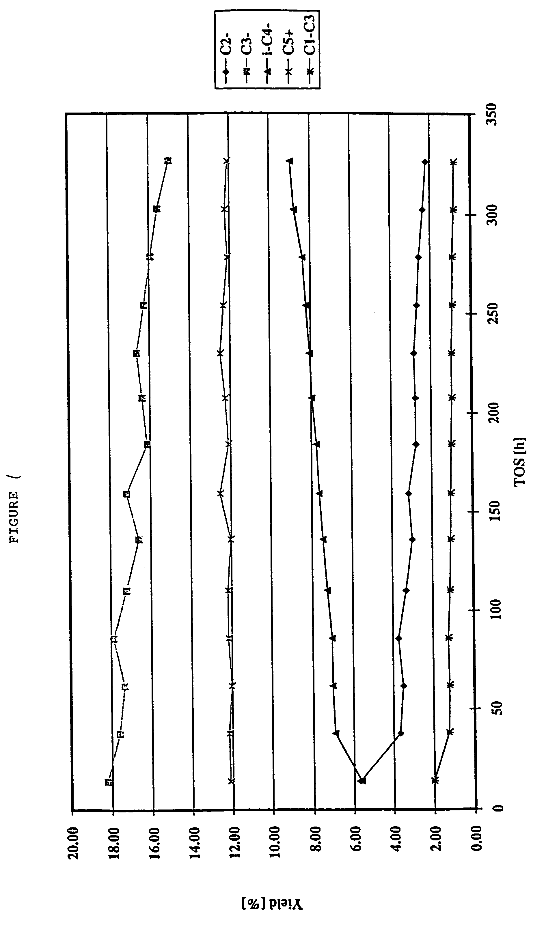
[0082]In this example, a light cracked naphtha (LCN) was cracked over a crystalline silicate. The catalyst was silicalite, formulated with a binder, which had been subjected to a pre-treatment (as described hereinbelow) by being heated (in steam), subjected to a de-alumination treatment with a complex for aluminum thereby to extract aluminum therefrom, and finally calcined. Thereafter the catalyst was employed to crack olefins in a hydrocarbon feedstock with the effluent produced by the catalytic cracking process having substantially the same olefin content as in the feedstock.
[0083]In the pre-treatment of the catalyst, a silicalite available in commerce under the trade name S115 from the company UOP Molecular Sieve Plant of P.O. Box 11486, Linde Drive, Chickasaw, Ala. 36611, USA was extruded into pellets with a binder comprising precipitated silica, the binder comprising 50 wt % of the resultant silicalite / binder combination. In greater detail, 538 g of precipitated silica (availab...
example 2
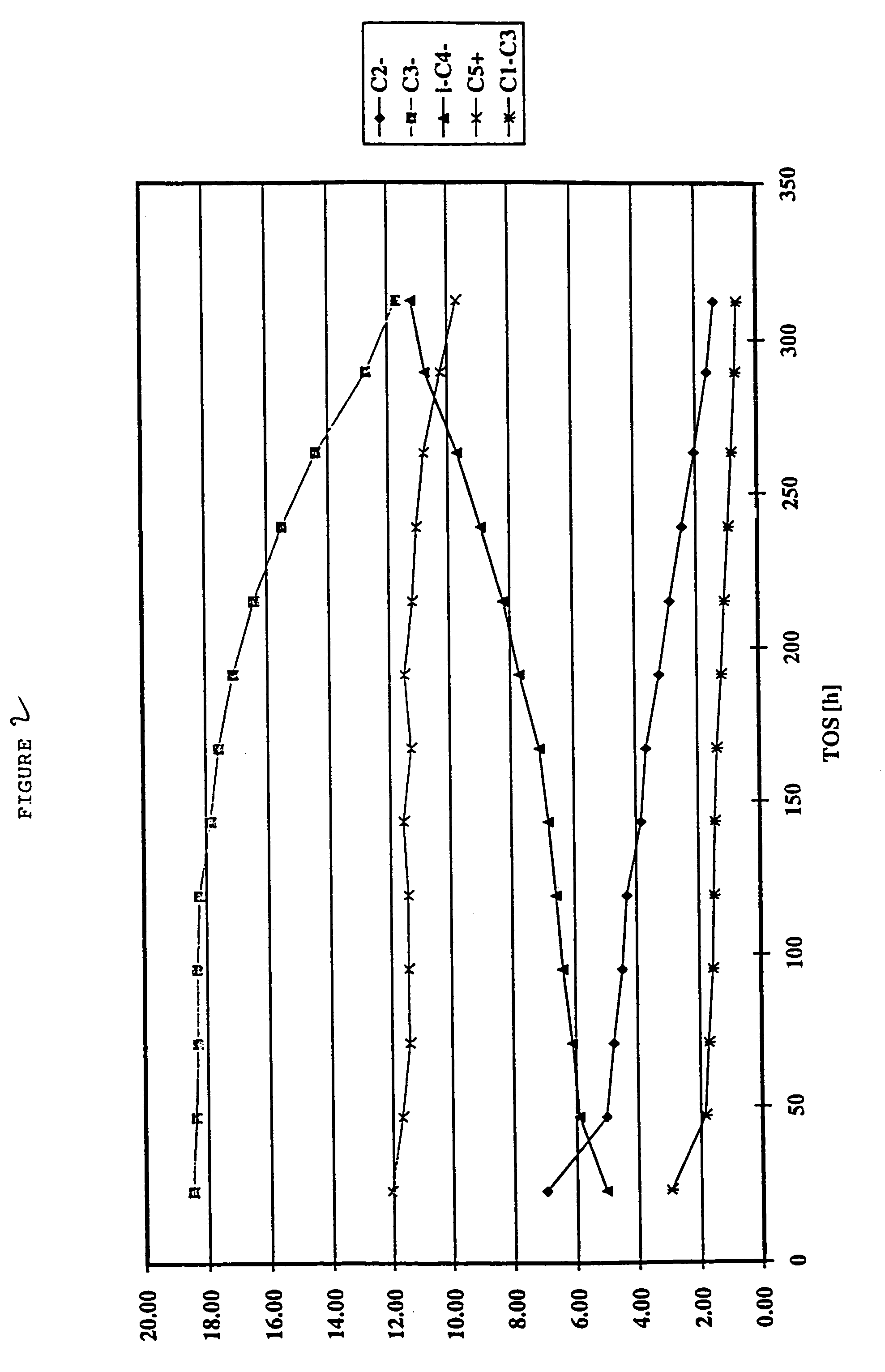
[0096]Example 1 was repeated but using a different feedstock comprising, rather than a light cracked naphtha, a fractionated C5 cut from a light cracked naphtha. In addition, in the catalytic cracking process the inlet temperature was 548° C. The hydrocarbon outlet pressure was around 1 bar (i.e. atmospheric pressure).
[0097]Table 4 shows the distribution of the hydrocarbon species in the feed of the C5 cut from the LCN, in the hydrotreated feed which had been subjected to a diene hydrogenation process as in Example 1, and in the effluent after the cracking process. It may be seen that the feed substantially initially comprises C5 species and that following the catalytic cracking process, the olefin content has remained substantially the same but the amount of C5 species in the effluent is significantly decreased as compared to the amount of such species in the initial feedstock. Again, the C2 to C4 lighter olefins may readily be fractionated from the effluent, leaving a C5+ liquid p...
example 3
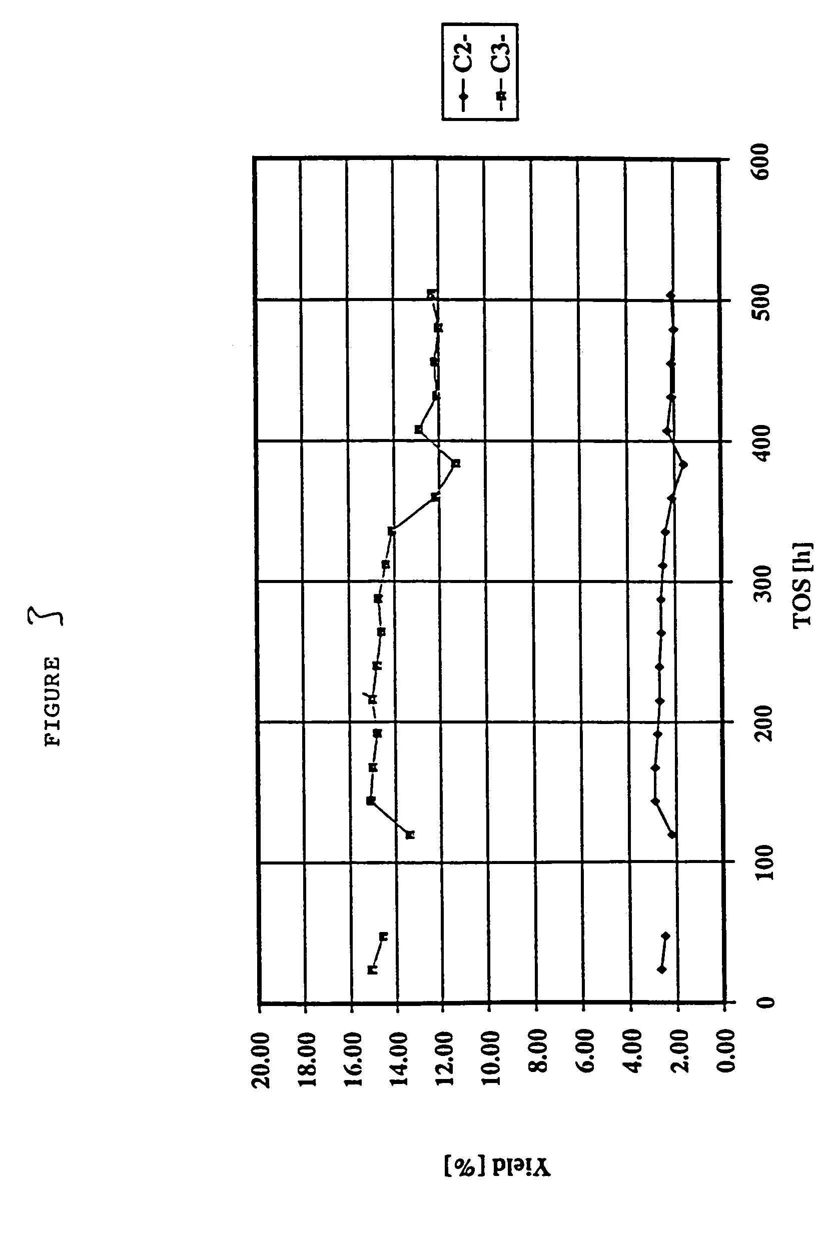
[0099]Example 1 was repeated but using as the feedstock, instead of a light cracked naphtha, a C4 raffinate (raffinate II) from an MTBE unit in a refinery. In addition, the inlet temperature of the feedstock was around 560° C. The hydrocarbon outlet pressure was around 1 bar (atmospheric pressure).
[0100]It may be seen from Tables 7 to 9 that C2 and primarily C3 olefins are produced from the C4 olefinic feedstock in accordance with the invention. In the effluent, around 34.5% of the olefin content is present as C2 and / or C3 olefins. The C2 and / or C3 olefins may be readily be fractionated from the effluent. The propylene yield on an olefin basis was 29%.
PUM
 Abstract
Description
Claims
Application Information
 - R&D
- Intellectual Property
- Life Sciences
- Materials
- Tech Scout
- Unparalleled Data Quality
- Higher Quality Content
- 60% Fewer Hallucinations
Browse by: Latest US Patents, China's latest patents, Technical Efficacy Thesaurus, Application Domain, Technology Topic, Popular Technical Reports.
© 2025 PatSnap. All rights reserved.Legal|Privacy policy|Modern Slavery Act Transparency Statement|Sitemap|About US| Contact US: help@patsnap.com


