
Coplanar waveguide biosensor for detecting molecular or cellular events

a biosensor and coplanar waveguide technology, applied in the field of biosensors, can solve the problems of relatively low frequency range over which the biosensor can be used, and suffer from the capacitor-type biosensor

Inactive Publication Date: 2006-08-01
DH TECH DEVMENT PTE +1
View PDF10 Cites 10 Cited by
  • Summary
  • Abstract
  • Description
  • Claims
  • Application Information

AI Technical Summary

Benefits of technology

[0005]The present invention provides a broadband coplanar waveguide biosensor for detecting molecular or cellular events. In one embodiment, the coplanar waveguide biosensor includes a one-port coplanar waveguide transmission line and a sample containment structure. The one-port coplanar waveguide transmission line is operable to support the propagation of an electromagnetic signal and includes a signal line and one or more spaced-apart ground elements. The signal line is configured to conduct a time-varying voltage, and the one or more ground elements are configured to maintain a time-invariant voltage, a detection region being formed between a portion of the signal line and a portion of at least one of the one or more ground elements. The sample containment structure intersects the detection region of the one-port coplanar waveguide transmission line and includes a cavity configured to hold 1 ml or less of sample solution within the detection region. The coplanar waveguide architecture of the described biosensor enables operation at frequencies higher than previously presented.

Problems solved by technology

The capacitor-type biosensor suffers from some disadvantages, one being the relatively low frequency range over which the biosensor can be used.

Method used


Image

  • Coplanar waveguide biosensor for detecting molecular or cellular events
  • Coplanar waveguide biosensor for detecting molecular or cellular events
  • Coplanar waveguide biosensor for detecting molecular or cellular events

Examples


first embodiment

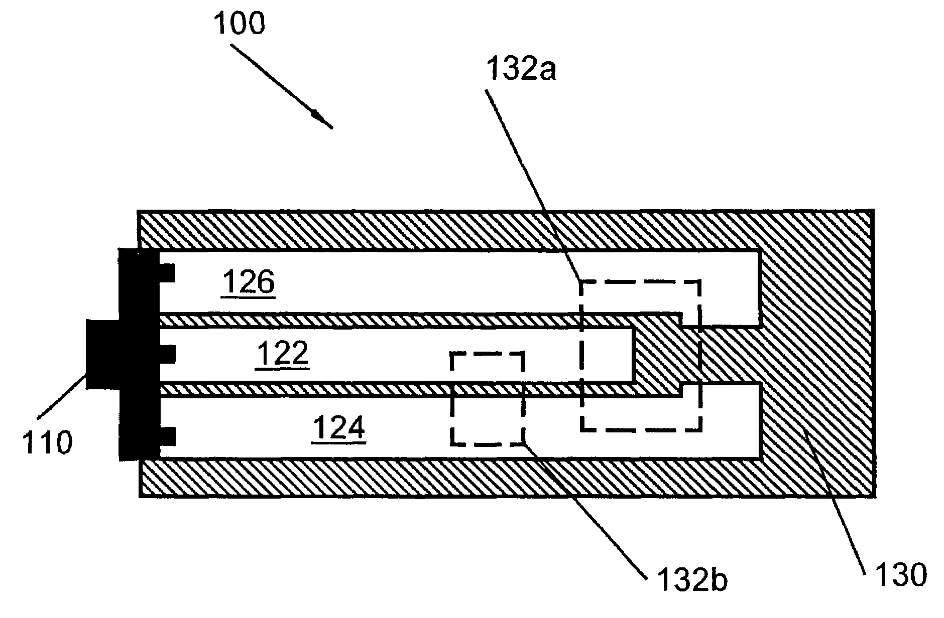
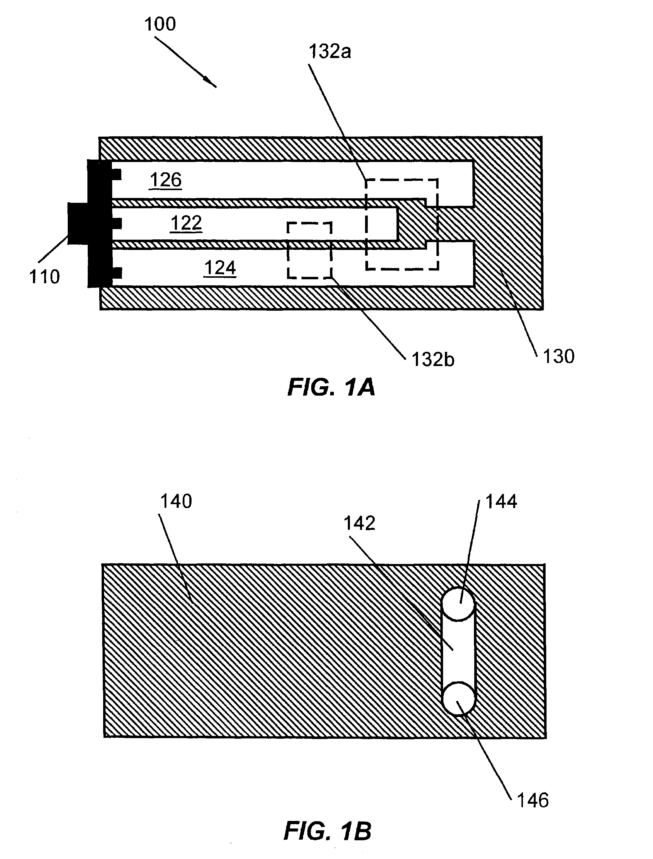
[0027]FIG. 1A illustrates top view of the coplanar waveguide biosensor 100 in accordance with the present invention. The biosensor 100 includes a coplanar waveguide transmission line 120 (referred to as a “cpw line”) in a one port configuration, the cpw line 120 comprised of a signal line 122 located between two ground elements 124 and 126 all of which are electrically coupled to a connector 110. The signal line 122 and ground elements 124 and 126 are formed on a dielectric substrate 130, which may consist of a variety of relatively low loss electrically insulating materials such as glass, fused silica, diamond, beryllium, sapphire, polyimide, alumina, quartz, silicon dioxide, gallium arsenide, woven dielectrics, or other similar materials. The signal line 122 and the ground elements 124 and 126 can be formed from a number of compounds using a variety of deposition techniques. In a specific embodiment, the dielectric substrate 130 is composed of borosilicate glass (εr≈4.6), the sign...

second embodiment

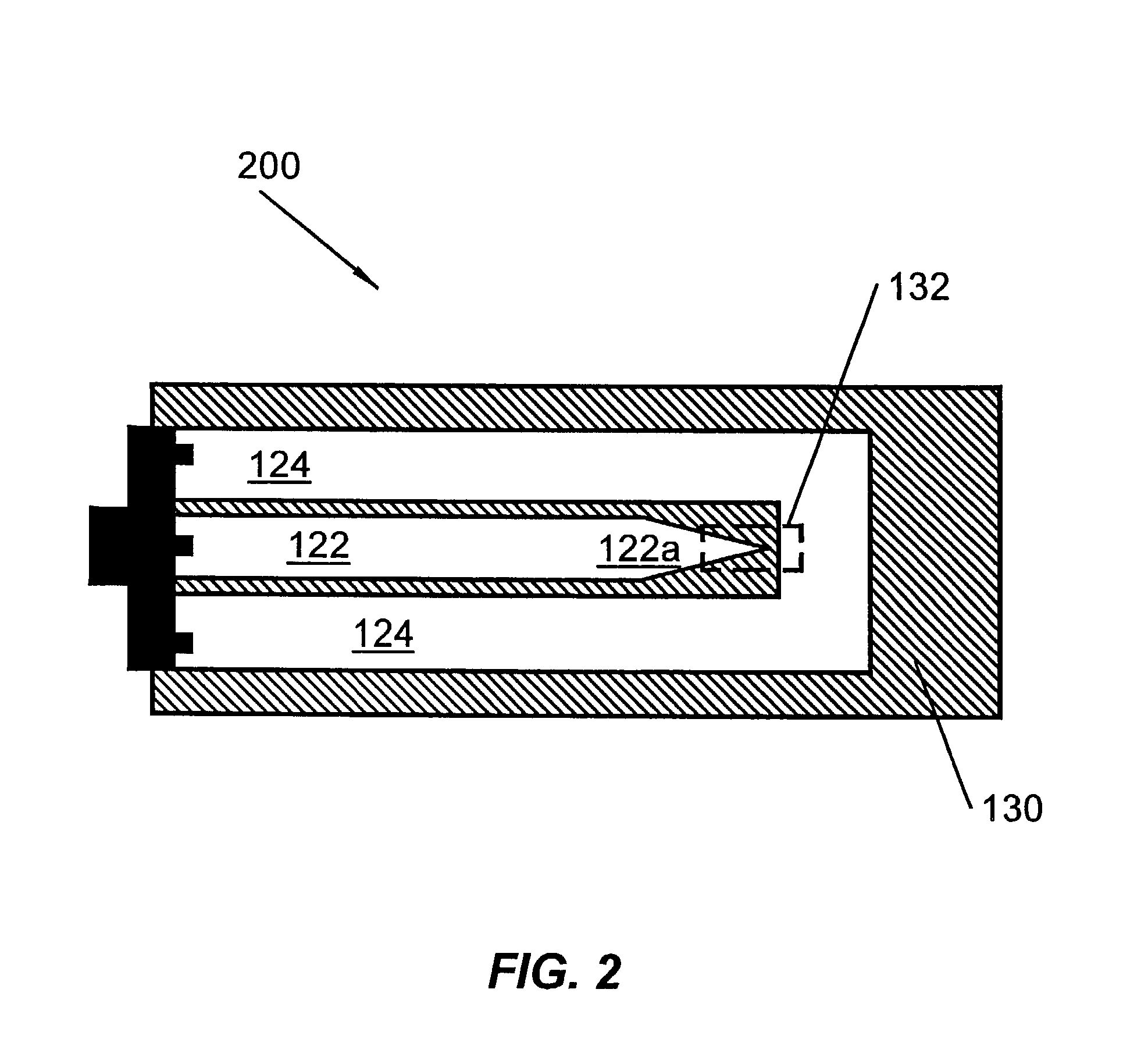
[0035]FIG. 2 illustrates top view of the coplanar waveguide biosensor 200 in accordance with the present invention. In this embodiment, the signal line 122 includes a tapered section 122a which terminates in a sharp point proximate to a ground element 124 that extends around the signal line 122. The detection region 132 is formed over the area where the tapered point of the signal line 122 most closely approaches the ground element 124. When a signal is propagated along the cpw line 120, the tapered shape and proximity of the signal line 122 to the ground element 124 will create a high intensity E-field between the tip of the tapered section 122a and the opposing section of the ground element 124. The high intensity E-field results in improved event detection sensitivity for the supplied sample. The illustrated taper is not exhaustive of the geometries possible and other shapes such as large angle bends, miters, curved shapes, or other structures may be used in alternative embodimen...

third embodiment

[0036]FIG. 3 illustrates top view of the coplanar waveguide biosensor 300 in accordance with the present invention. As illustrated, both the signal line 122 and the ground element 124 includes tapered sections 122a and 124a, respectively, the area between them defining a detection region 132. By tapering both line sections, an even higher E-field intensity is created and greater event detection sensitivity achieved. The reader will appreciate that these are but a few of the various modification possible and other configurations are possible under alternative embodiments under the present invention. As above, any of the aforementioned sample containment structures or modifications thereof may be adapted for use with this biosensor.


PUM

PropertyMeasurementUnit
Volumeaaaaaaaaaa
Frequencyaaaaaaaaaa
Frequencyaaaaaaaaaa

Abstract

A coplanar waveguide biosensor and methods of use include a coplanar waveguide transmission line and a sample containment structure. The coplanar waveguide transmission line is operable to support the propagation of an electromagnetic signal and includes a signal line and one or more spaced apart ground elements. The signal line is configured to conduct a time-varying voltage, and the one or more ground elements are configured to maintain a time-invariant voltage, a detection region being formed between a portion of the signal line and a portion of at least one of the one or more ground elements. Detection methods are improved through the enhancement of the electric field in the detection region via impedance discontinuities in the signal line and ground elements. The sample containment structure intersects the detection region of the coplanar waveguide transmission line and includes a cavity configured to hold 1 ml or less of sample solution within the detection region.

Description

CROSS REFERENCE TO RELATED APPLICATIONS[0001]This patent application is a continuation-in-part of U.S. patent application Ser. No. 09 / 929,521 filed Aug. 13, 2001 now abandoned, which is a continuation-in-part of application Ser. No. 09 / 365,978 now U.S. Pat. No. 6,485,905, filed Aug. 2, 1999 and issued Nov. 26, 2002, which is a continuation-in-part of application Ser. No. 09 / 243,194 U.S. Pat. No. 6,368,795, filed Feb. 1, 1999 and issued Apr. 9, 2002, which claims the benefit of U.S. Provisional application No. 60 / 073,445, filed Feb. 2, 1998 and now abandoned.BACKGROUND OF THE INVENTION[0002]The present invention relates to biosensors and more particularly to coplanar waveguide biosensors configured to detect molecular or cellular events.[0003]A number of bioelectric sensors are known in the biotechnical arts and use electronic signals to detect and identify the structure and interactions of molecules, as well as cellular function and activity. In the past, bioelectric sensors (“biose...

Claims


Application Information

Patent Timeline
IPC IPC(8): G01N33/543C12Q1/00G01N23/04
CPCC12Q1/001G01N23/046G01N33/54373G01N33/5438G01N2223/419Y10S436/805Y10S436/806
Inventor HEFTI, JOHN J.BARTELL, BARRETTKRAMER, KURTRHODES, MARK A.
Owner DH TECH DEVMENT PTE
Learn More