Method for simultaneous two-disk texturing

a texturing method and disk technology, applied in the direction of lapping machines, instruments, applications, etc., to achieve the effect of substantial capital equipment savings and increased output in the production of finished disks

Inactive Publication Date: 2006-08-01
SEAGATE TECH LLC
View PDF78 Cites 2 Cited by
  • Summary
  • Abstract
  • Description
  • Claims
  • Application Information

AI Technical Summary

Benefits of technology

[0030]These and other benefits are addressed by the various embodiments and configurations of the present invention. For example, a benefit provided by the present invention is an increased output in the production of finished disks achieved by texturing two single-sided disks simultaneously. Another benefit is that, with limited modifications, the present invention can process pairs of single-sided disks utilizing existing processing equipment originally designed and built to texture double-sided disks. This results in substantial capital equipment savings which would otherwise be spent unnecessarily modifying existing equipment or creating new equipment to process single-sided disks. Moreover, as should be appreciated from a review of the specification and referenced drawings, the present invention has applicability in data zone texturing processes and laser zone texturing processes.
[0032]To prevent relative movement or slippage between the disks during data zone texturing, it may be desirable to submerge the disk carrier in a liquid, such as water, in order that a liquid film is positioned between the disks prior to merging the pair of disks into a concentric contact merge orientation. The liquid film will act as an adhesive and facilitate unified movement of the disks. This promotes consistent and uniform texturing of each disk.
[0035]The demerge methods and apparatus may vary depending upon how the disks are textured. This is primarily due to the fact that the force required to separate or demerge disk pairs is proportional to the force applied against the disks during texturing. In other words, disks which are pressed or forced together are harder to separate than disks that are not forced together. Thus, because the data zone texturing process applies a relatively large force against the disk surfaces, a relatively large force is needed to separate the disks. To reduce the possibility of damaging the disks, the demerge force is preferably spread or dispersed over a larger area of the disk perimeter by configuring the demerge tool to act upon a greater surface area. Conversely, because the forces applied to the disk surfaces during laser zone texturing are substantially smaller, the demerge tools can be smaller and can apply a smaller force over a smaller area of the disk perimeters.

Problems solved by technology

This results in substantial capital equipment savings which would otherwise be spent unnecessarily modifying existing equipment or creating new equipment to process single-sided disks.

Method used


Image

  • Method for simultaneous two-disk texturing
  • Method for simultaneous two-disk texturing
  • Method for simultaneous two-disk texturing

Examples


Embodiment Construction

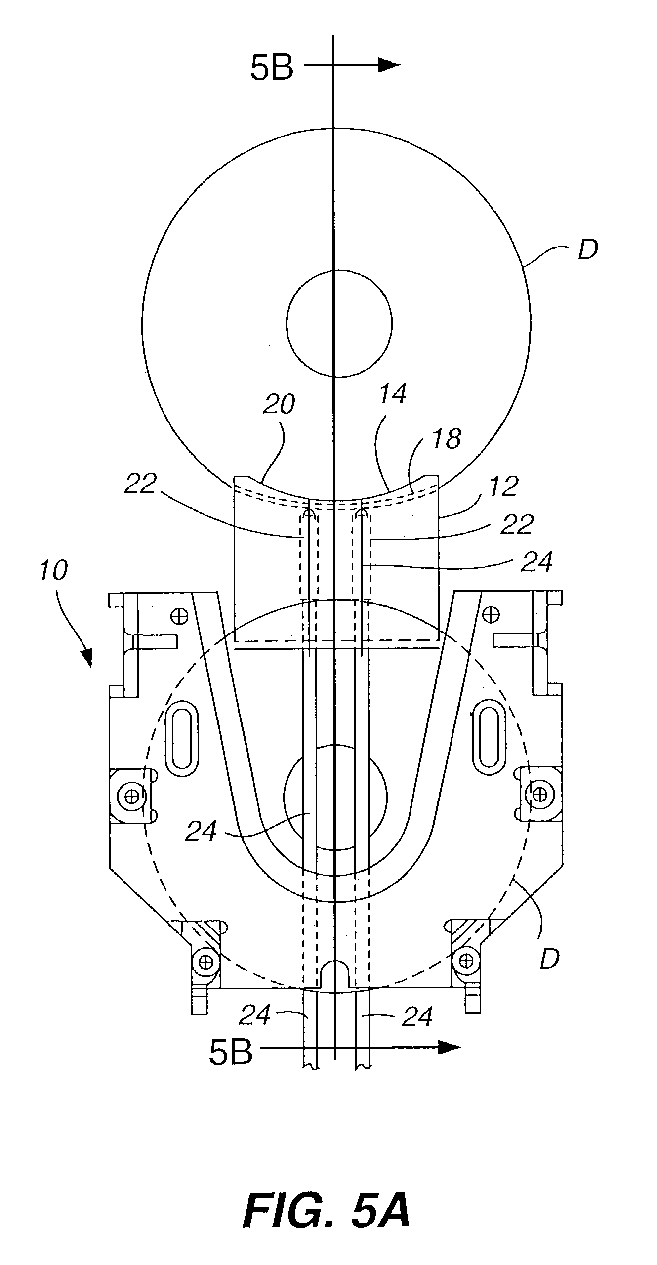
[0080]Turning to FIGS. 5A, 5B, a cassette 10 is shown holding multiple pairs of gap merge disks D. The apparatus dimensions discussed herein relate to 95 millimeter diameter disks having a thickness of about 0.050 inches, unless otherwise stated. The spacing between disks of this size in a gap merge pair is preferably about 0.035 inches, although the space can extend from about 0.025 inches and larger. It should be understood that the apparatus and method of the present invention will work with disks of different diameters and thicknesses, in which case dimensions may vary from those stated herein. The gap merge orientation of the pairs of disks is best illustrated in FIG. 5B.

[0081]As shown in FIGS. 5A and 5B, one embodiment of a lift saddle 12 is utilized to remove and return pairs of disks from and to the cassette. The lift saddle 12 has an arcuate shaped disk engaging portion 14 comprising two channels or grooves 16 separated by a raised center ridge or tooth 18 (FIGS. 6–9). The ...


PUM

PropertyMeasurementUnit
Lengthaaaaaaaaaa
Lengthaaaaaaaaaa
Perimeteraaaaaaaaaa

Abstract

Various methods and apparatus for simultaneously texturing two single-sided hard memory disks is provided. The two disks are placed in a concentric contact merge orientation such that the outwardly facing surface of each disk may be simultaneously subjected to texturing by equipment designed to texture one double-sided disk.

Description

CROSS REFERENCE TO RELATED APPLICATIONS[0001]Priority is claimed from U.S. Provisional Patent Application Ser. Nos. 60 / 417,623 and 60 / 417,711, both filed Oct. 10, 2002, which are incorporated by reference herein in their entirety.[0002]The subject matter of the present application is related to the following applications, each of which has a filing date of May 9, 2003: U.S. patent application Ser. No. 10 / 434,550 entitled “Single-Sided Sputtered Magnetic Recording Disks” in the name of Clasara et al. (Publication No. US-2003-0211361-A1); U.S. patent application Ser. No. 10 / 435,361 entitled “Dual Disk Transport Mechanism Processing Two Disks Tilted Toward Each Other” in the name of Grow et al. (Publication No. US-2003-0208899-A1); U.S. patent application Ser. No. 10 / 435,358 entitled “Information-Storage Media With Dissimilar Outer Diameter and / or Inner Diameter Chamfer Designs On Two Sides” in the name of Clasara et al. (Publication No. US-2003-0210498-A1); U.S. patent application Ser...

Claims


Application Information

Patent Timeline
IPC IPC(8): B24B1/00B24B7/22B24B37/08G11B5/82G11B5/84G11B23/00
CPCB24B7/228B24B19/028G11B23/00G11B5/8404B24B37/08G11B5/82
Inventor BUITRON, GERARDOCROFTON, WALTEROKAMOTO, BARRYSAGEN, LYNNETTE A.TA, NGHIA
Owner SEAGATE TECH LLC
Why Eureka
Try Eureka