
Hydraulic continuously variable transmission

a transmission device and continuously variable technology, applied in the direction of fluid couplings, gearings, couplings, etc., can solve the problems of affecting the side of the electric pump and the side of the pump and the motor, and the servo device of the wash plate is liable to project more in the side direction, and achieves the effect of small width

Inactive Publication Date: 2006-07-18
HONDA MOTOR CO LTD
View PDF8 Cites 11 Cited by
  • Summary
  • Abstract
  • Description
  • Claims
  • Application Information

AI Technical Summary

Benefits of technology

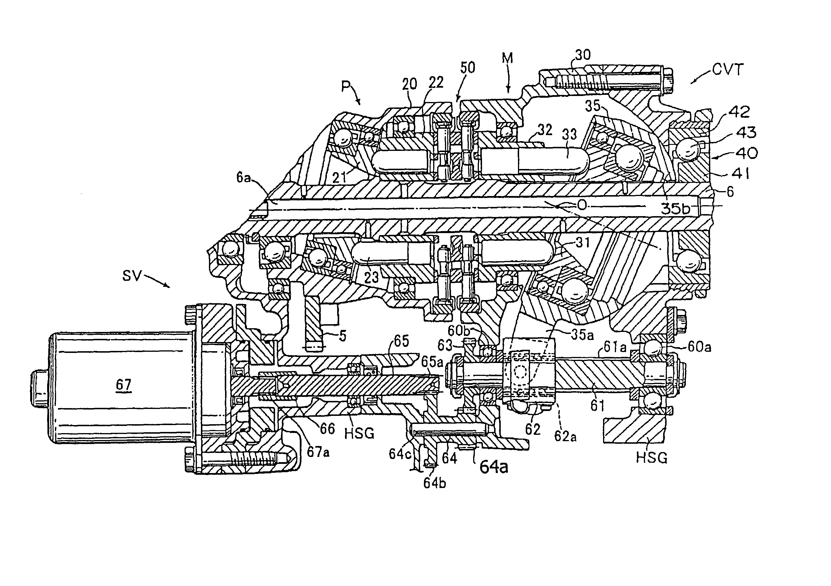
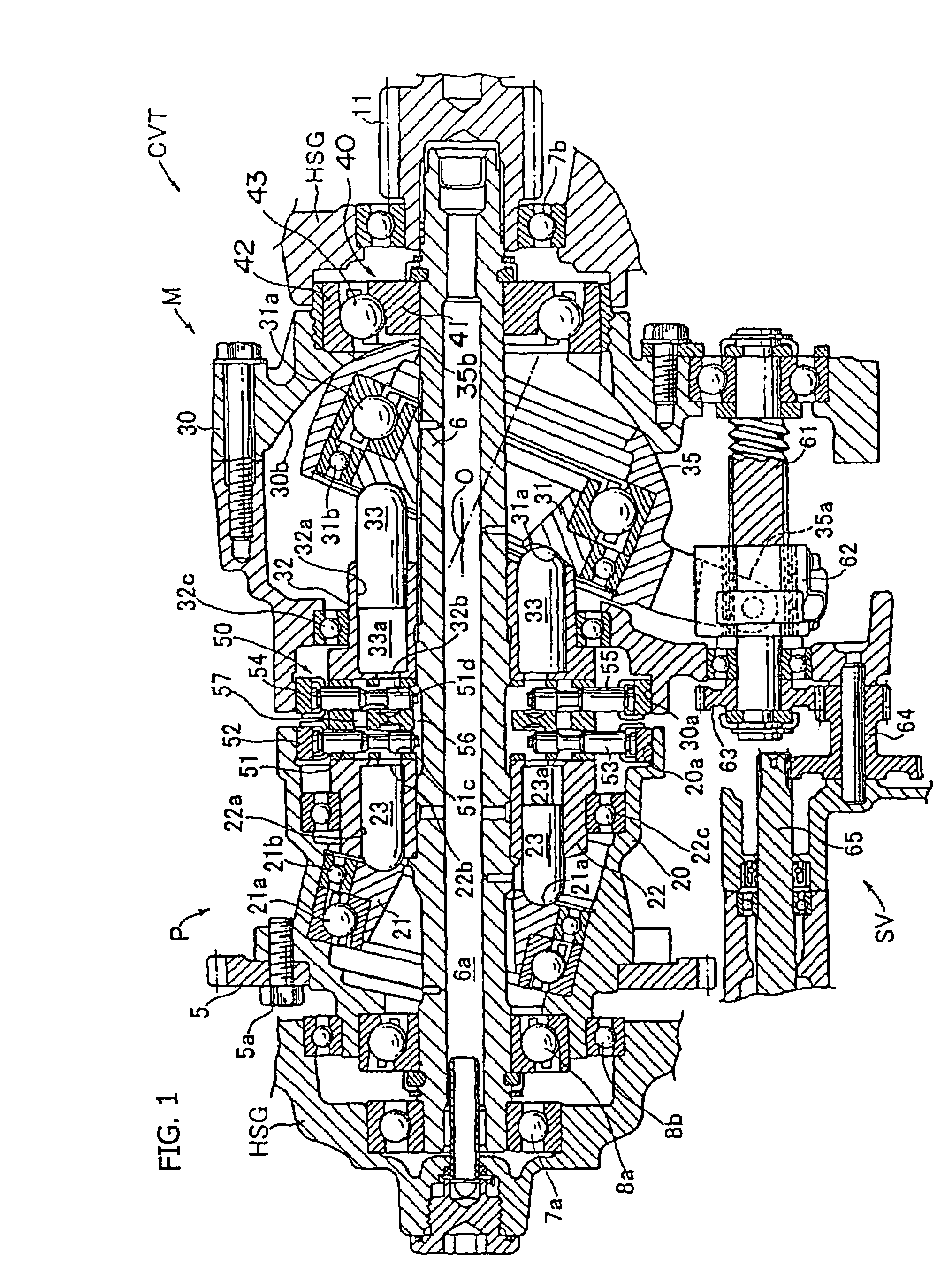
[0014]The present invention has been made in consideration of the above problems. Accordingly, it is an object of the present invention to provide a hydraulic continuously variable transmission in which the amount of projection in a radial direction of a swash plate servo device for pivotally adjusting a motor swash plate can be reduced and which is compact with a small width.
[0015]It is another object of the present invention to provide a hydraulic continuously variable transmission so configured that a servo motor (swash plate control motor) constituting a swash plate servo device is less liable to be affected by heat coming from the side of a pump and a motor.
[0019]According to the hydraulic continuously variable transmission constituted as above, since the servo motor and the input gear are disposed close to each other to such an extent that they overlap partly with each other in side view, the amount of projection of the swash plate adjustment mechanism in a radial direction can be reduced, and a compact hydraulic continuously variable transmission with a small width can be obtained.
[0022]Furthermore, by connecting the servo motor to the swash plate adjustment mechanism through the spacer shaft, it is possible to dispose the servo motor axially away from a lateral side of the pump and motor, and to ensure that the servo motor is less liable to be affected by any heat coming from the side of the pump and motor.
[0023]In addition, it is preferable that the rotation of the spacer shaft is transmitted to the swash plate adjustment mechanism through an idle gear train. This makes it possible, for example, to arbitrarily set the position of the swash plate adjustment mechanism (the screw shaft in the embodiment) and the position of the servo motor, and to increase the degree of freedom in arrangement layout. Furthermore, it is possible to freely set the rotating speed ratio of the swash plate adjustment mechanism (screw shaft) relative to the rotation of the servo motor, i.e., transmission ratio, by changing the gear ratios in the idle gear train.

Problems solved by technology

Particularly, in the case of the above-mentioned hydraulic continuously variable transmission, an input gear (primary driven gear) for receiving the rotational drive force from the engine is attached to the outer circumference of a pump casing of the hydraulic pump, and the input gear projects outwards in the radial direction, resulting in the problem that the swash plate servo device is liable to project more in a side direction so as to obviate interference with the input gear.
In addition, since the servo motor composed of an electric motor is disposed in the vicinity of a lateral side of the swash plate plunger pump and motor, the electric pump is liable to be affected by any heat coming from the side of the pump and motor.

Method used


Image

  • Hydraulic continuously variable transmission
  • Hydraulic continuously variable transmission
  • Hydraulic continuously variable transmission

Examples


Embodiment Construction

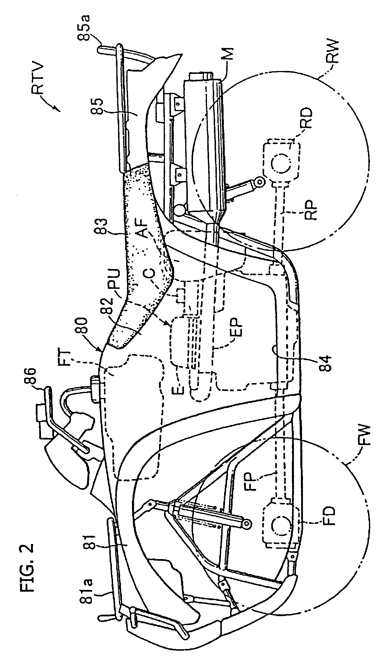
[0033]Now, an embodiment of the present invention will be described below referring to the drawings. First, FIGS. 2 to 4 show a rough terrain vehicle RTV including a hydraulic continuously variable transmission according to the present invention. The vehicle RTV includes a power unit PU incorporated in a vehicle body 80 having a frame structure therein, and left and right front and rear wheels FW and RW driven upon receiving the output of the power unit PU.

[0034]In addition, the vehicle body 80 includes a front fender portion 81 including a front guard 81a and located at a vehicle body front portion, a saddle portion 82 raised upwards and extending in the front-rear direction at a vehicle body central portion, left and right step portions 84, 84 extending in the left-right direction at left and right lower portions of the saddle portion 82, and a rear fender portion 85 including a rear guard 85a and located at a vehicle body rear portion, and the saddle portion 82 is provided with a...


PUM


Abstract

To reduce the projection of a swash plate servo mechanism in the radial direction, and to make a hydraulic continuously variable transmission compact, a swash plate plunger pump includes a pump casing provided with an input driven gear. A pump cylinder and a motor cylinder are connected to a transmission output shaft, and a motor pivot member provided with a motor swash plate member is supported to be pivotally movable. A motor servo mechanism includes a ball screw shaft, a ball nut to which an end portion of the motor pivot member is connected, and a swash plate control motor to rotate the screw shaft. A swash plate control motor, located on the side of a hydraulic pump relative to the input driven gear, is mounted to the outside surface of a transmission housing close to the center axis side of a transmission output shaft.

Description

CROSS-REFERENCE TO RELATED APPLICATIONS[0001]The present invention claims priority under 35 USC 119 based on Japanese patent application No. 2003-096813, filed Mar. 31, 2003.BACKGROUND OF THE INVENTION[0002]1. Field of the Invention[0003]The present invention relates to a hydraulic continuously variable transmission. More particularly, the present invention relates to a hydraulic continuously variable transmission including a swash plate plunger pump and a swash plate plunger motor connected to each other through a closed hydraulic circuit, and particularly to a hydraulic continuously variable transmission including a swash plate servo device for pivotally adjusting a swash plate member of a swash plate plunger motor.[0004]2. Description of the Background Art[0005]As to hydraulic continuously variable transmissions including a hydraulic pump and a hydraulic motor in combination, a variety of forms of configurations have been known and put to practical use.[0006]One example of a comm...

Claims


Application Information

Patent Timeline
IPC IPC(8): F16D39/00F16H3/14F16H39/14F16H47/02
CPCF16H39/14F16H3/14
Inventor ITO, KATSUHIKOKOYAMA, SHINYAYASUDA, KAZUHIRO
Owner HONDA MOTOR CO LTD
Learn More