
Noncontact sensitivity and compliance calibration method for cantilever-based insturments

Inactive Publication Date: 2006-06-27
OXFORD INSTRUMENTS +1
View PDF7 Cites 4 Cited by
  • Summary
  • Abstract
  • Description
  • Claims
  • Application Information

AI Technical Summary

Benefits of technology

[0025]An object of the present invention is to provide a simple method for calibrating the sensitivity of any type of cantilever used in cantilever-based instruments without making contact with any surface.
[0027]Another objective is to provide a method for calibrating the sensitivity of cantilevers that is easily automated.

Problems solved by technology

The conventional methods for determining optical lever sensitivity have either been destructive or required that the lever be brought into hard contact with a well-defined rigid surface.
Because the distances are typically less than one micron, and the relative positions of the cantilever tip and such a surface difficult to locate, making such contact is far from a trivial proposition.
The difficulty of the procedure is enhanced by the fact that slippage of the tip laterally over the surface introduces serious errors.
Even if the conventional methods were easy of execution, there are many instances when it is not desirable or convenient to measure optical lever sensitivity by touching a surface.
When the results depend on chemical or biological sensitization of the cantilever tip, or if the tip is particularly sharp, hard contact or any contact before performing the experiment may compromise the results.
Similarly compromising may be hard contact when the sample is coated on the surface and is a soft material such as cells.
Two methods for determining optical lever sensitivity not requiring hard contact with a well-defined rigid surface have been proposed, but each has important limitations and is as yet untested.
Because it is not sensitive to actual motion of the cantilever, this method does not account for differences in cantilever geometry or changes in the alignment of the spot on the lever.
These issues become even more critical as the length scale of cantilevers shrink.
Although there has been a large amount of work dedicated to the cantilever calibration issue, the precision of the resulting techniques seems to be limited to 10%.

Method used


Image

  • Noncontact sensitivity and compliance calibration method for cantilever-based insturments
  • Noncontact sensitivity and compliance calibration method for cantilever-based insturments
  • Noncontact sensitivity and compliance calibration method for cantilever-based insturments

Examples


Embodiment Construction

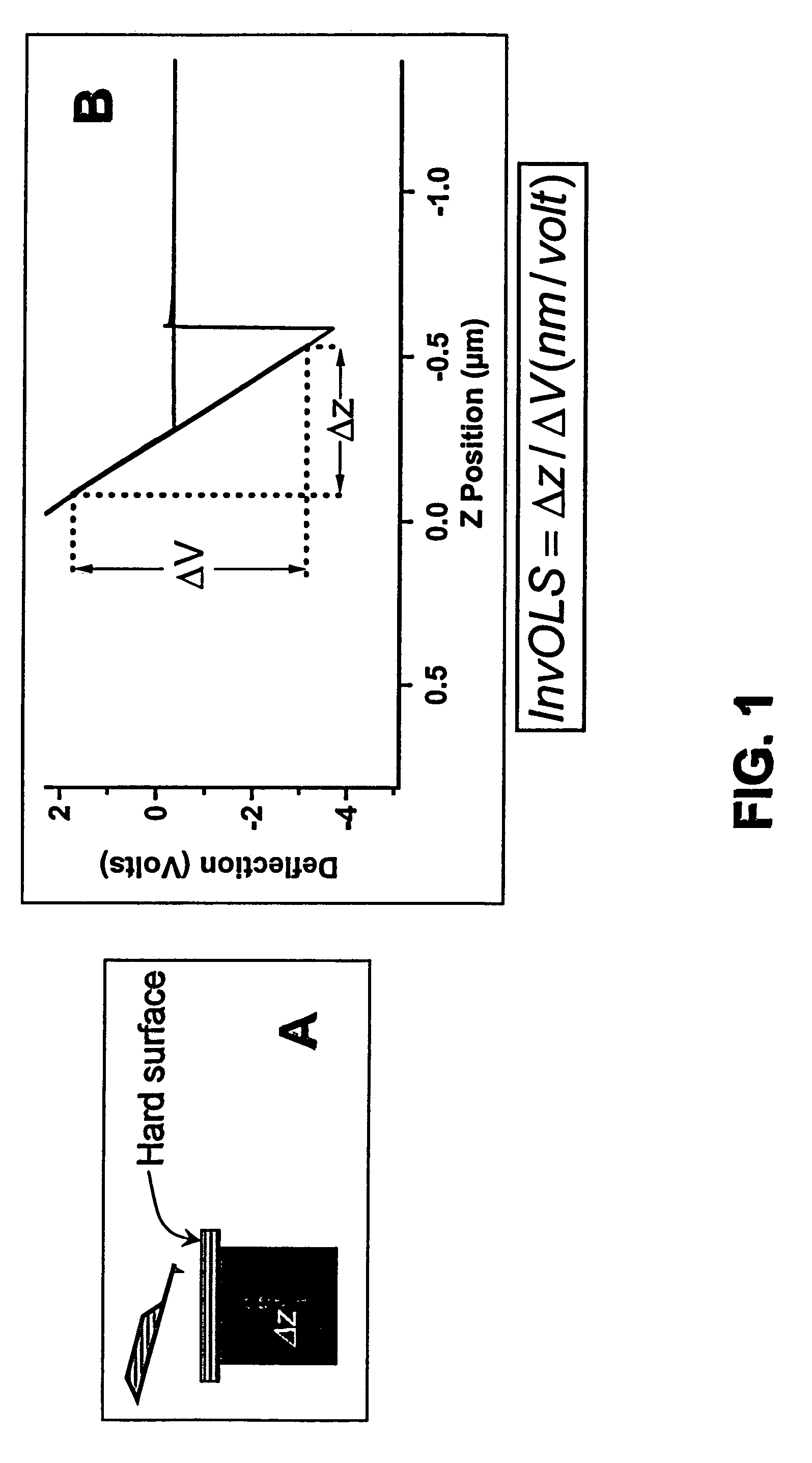
[0041]The optical sensitivity of the micromachined cantilever, the derivative of the change in cantilever deflection with respect to change in the z position of the cantilever tip (typically abbreviated as “OLS”), is the foundation for correctly interpreting the results obtained from cantilever-based instruments. FIG. 1A depicts one of the conventional methods for determining OLS. As shown in the panel, the cantilever is pressed into a hard surface (typically freshly cleaved mica) by the instrument (not shown) and moved an arbitrary distance measured by the instrument. Deflection of the cantilever resulting from this change in position is measured with optical detection means commonly employed in such instruments: low coherence light is focused onto the back of the cantilever with an adjustable focus lens and the light reflecting off the cantilever is collected by an adjustable mirror and guided onto position sensor. The position sensor provides a voltage that is proportional to the...


PUM


Abstract

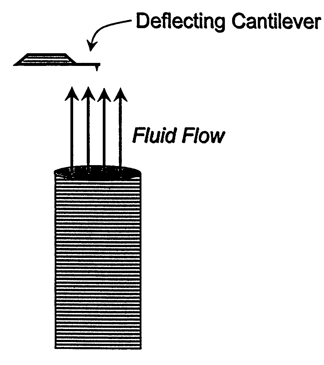
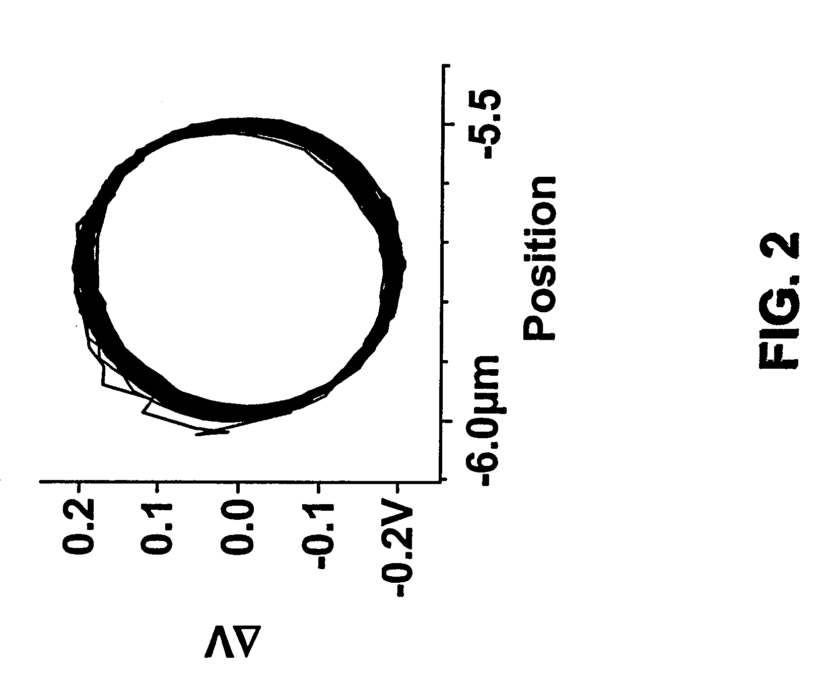
A method for determining physical properties of micromachined cantilevers used in cantilever-based instruments, including atomic force microscopes, molecular force probe instruments and chemical or biological sensing probes. The properties that may be so determined include optical lever sensitivity, cantilever spring constant and cantilever-sample separation. Cantilevers characterized with the method may be used to determine fluid flow rates. The method is based on measurements of cantilever deflection resulting from drag force as the cantilever is moved through fluid. Unlike other methods for determining such physical properties of cantilevers, the method described does not depend on cantilever contact with a well-defined rigid surface. Consequently, the method may be employed in situations where such contact is undesirable or inconvenient. The method has numerous applications, including molecular force measurements, atomic force microscopy and manipulation technology, chemical or biological sensing, [lithographic manufacturing, nanometer scale surface profiling] and other aspects of nanotechnology.

Description

CROSS-REFERENCE TO RELATED APPLICATIONS[0001]This application claims priority of U.S. Provisional Application No. 60 / 272,697, filed on Feb. 28, 2001, the disclosures of which are incorporated fully herein by reference.REFERENCES CITEDOther Publications[0002]Cleveland, J. P.; Manne, S.; Bocek, D.; Hansma, P. K. Rev. Sci. Instrum. 1993, 64.[0003]Walters, D. A.; Cleveland, J. P.; Thomson, N. H.; Hansma, P. K.; Wendman, M. A.; Gurley, G.; Elings, V. Rev. Sci. Instrum. 1996, 67, 3583–3590.[0004]T. J. Senden and W. A. Ducker, Langmuir 1994, 10, 1003–1004.[0005]C. J. Drummond and T. J. Senden, Mater. Sci. Forum 1995, 189–190, 107–114.[0006]Ogletree, D. F.; Carpick, R. W.; Salmeron, M. Rev. Sci. Instrum. 1996, 67, 3298–3306.[0007]Sader, J. E.; Larson, I.; Mulvaney, P.; White, L. R. Rev. Sci. Instrum. 1995, 66, 3789–3798.[0008]Sader, J. E. J. Appl. Phys. 1998, 84, 64–76.[0009]Neumeister, J. M.; Ducker, W. A. Rev. Sci. Instrum. 1994, 65, 2527–31.[0010]Scholl, D.; Everson, M. P.; Jaklevic, R. ...

Claims


Application Information

Patent Timeline
IPC IPC(8): G01B21/30G01B11/00G01B21/00G01B5/28G01N3/00G01N3/02G01N3/06G01N3/32G01Q40/00
CPCB82Y35/00G01B5/28G01N3/32G01Q40/00G01N2203/0005G01N2203/0075G01N2203/021G01N2203/0286G01N2203/0688G01N2203/0023
Inventor PROKSCH, ROGER
Owner OXFORD INSTRUMENTS
Learn More