
System and method for measuring lead impedance in an implantable stimulation device employing pulse-train waveforms

a pulse-train waveform and implantable technology, applied in the field of implantable cardioverter defibrillators, can solve the problems of lead failure, muscle twitching and sensation, and the lead impedance above 100 ohms is generally considered a sign of lead failure, so as to improve the accuracy of patient lead impedance measurement, the effect of reducing the patient's sensation and increasing the stimulation threshold

Inactive Publication Date: 2006-06-20
PACESETTER INC
View PDF20 Cites 87 Cited by
  • Summary
  • Abstract
  • Description
  • Claims
  • Application Information

AI Technical Summary

Benefits of technology

The present invention is an implantable stimulation device that uses a lead impedance measuring circuit to check the integrity of various leads implanted in a patient's dysfunctional heart. The device includes a pulse generator, electrodes, and leads for delivering electrical pulses to the heart. The device measures the voltage before and after the delivery of the pulse to calculate the resulting tissue impedance across the leads. The device generates a waveform composed of a first set of pulses with a first polarity and a second set of pulses with a second polarity that is opposite to the first polarity. The pulses have a duration less than 15% of the time constant of stimulation of the tissues. The device can generate multiple waveforms with higher accuracy and reduced sensation for the patient. The alternating polarities of the pulse-train waveform result in a higher stimulation threshold, reducing sensation for the patient. The shorter duration of each pulse also reduces polarization voltage across the electrode-electrolyte interface, improving the accuracy of the measured impedance.

Problems solved by technology

Since the lead is an essential part of the therapy a lead failure renders the device ineffective.
For high-voltage leads, a sudden rise of the lead impedance above 100 ohms is generally considered a signs of lead failure.
Several problems are associated with the monophasic detection waveform of FIG. 3.
In fact, such a duration almost approaches the time constant for stimulation of de-innervated muscles, and could thus cause muscle twitches and sensation.
However, this accuracy degrades when charging to, or measuring lower voltages.
This loss of accuracy is compounded by measurement errors associated with even lower voltages, and results in an inaccurate high-voltage lead integrity check of the lead impedance.
Another problem is that approximately 3 volts of the monophasic detection waveform is consumed in polarizing of the electrode-electrolyte interface at the electrodes and body fluids boundary.
This voltage drop occurs, for example, between the blood and a polished platinum electrode, obscuring the delivered signal and compounding the inaccuracy of the measurement of the lead impedances.
This results in reducing the patient's sensation associated with the delivery of a conventional waveform.

Method used


Image

  • System and method for measuring lead impedance in an implantable stimulation device employing pulse-train waveforms
  • System and method for measuring lead impedance in an implantable stimulation device employing pulse-train waveforms
  • System and method for measuring lead impedance in an implantable stimulation device employing pulse-train waveforms

Examples


Embodiment Construction

[0030]The following description is of a best mode presently contemplated for practicing the present invention. This description is not to be taken in a limiting sense but is made merely for the purpose of describing the general principles of the invention. The present invention is directed at an improved patient impedance measuring system for implantable cardiac stimulating devices with pacemaking, cardioversion, and / or defibrillation capabilities.

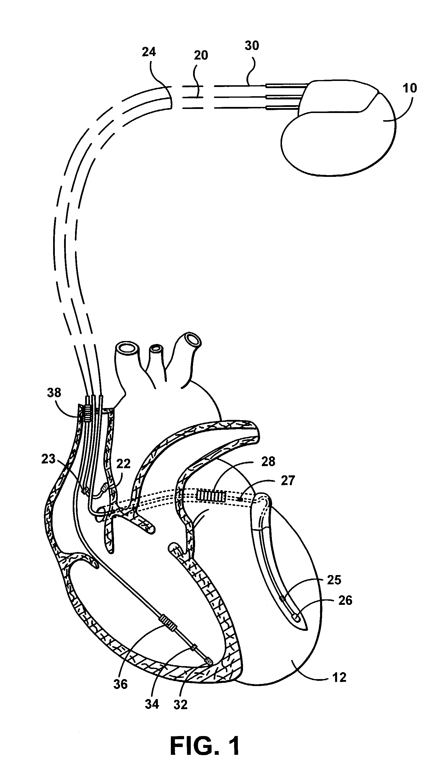
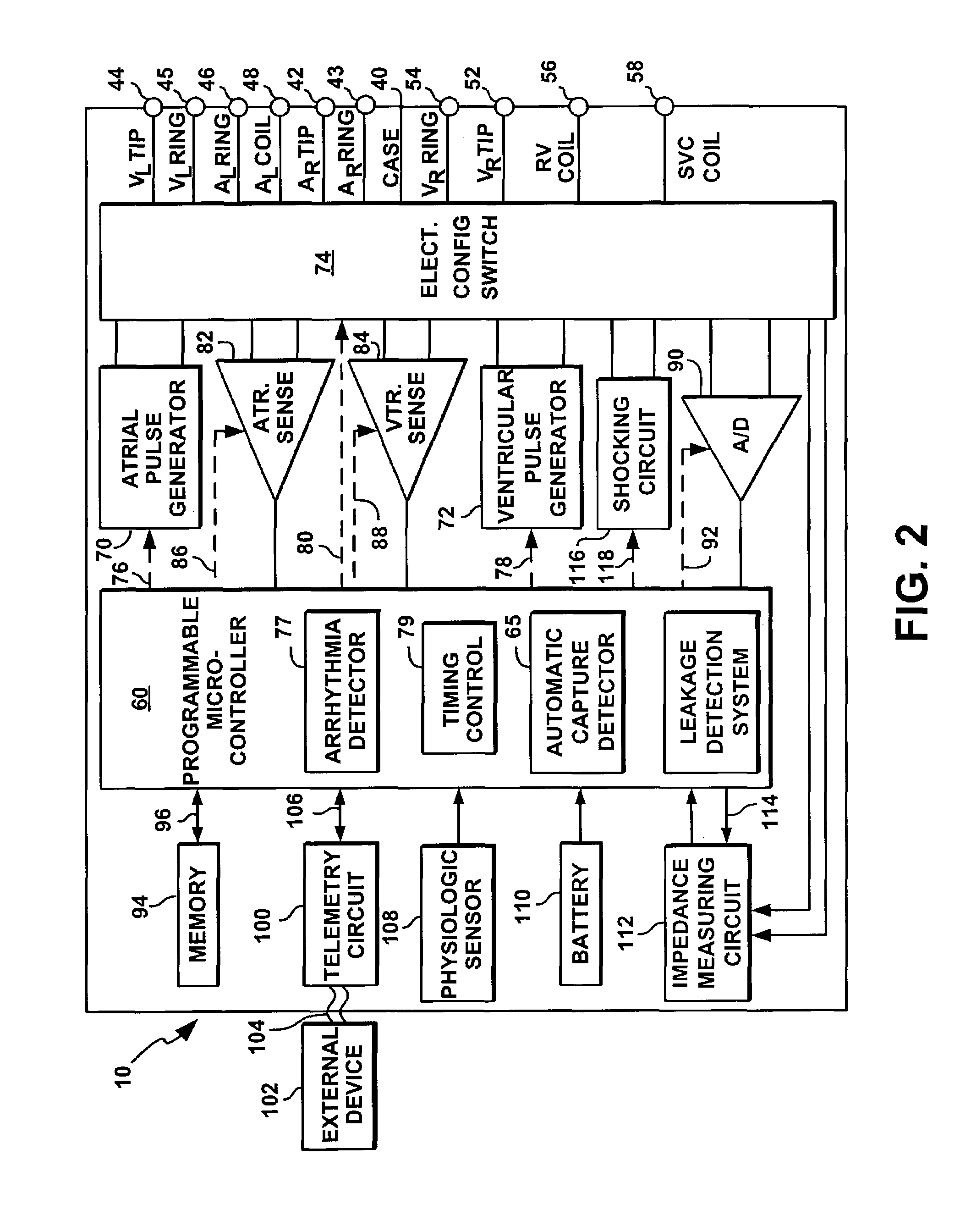
[0031]A cardiac stimulation device will thus be described in conjunction with FIGS. 1 and 2, in which the features included in this invention could be implemented. It is recognized, however, that numerous variations of such a device exist in which various methods included in the present invention can be implemented without deviating from the scope of the present invention.

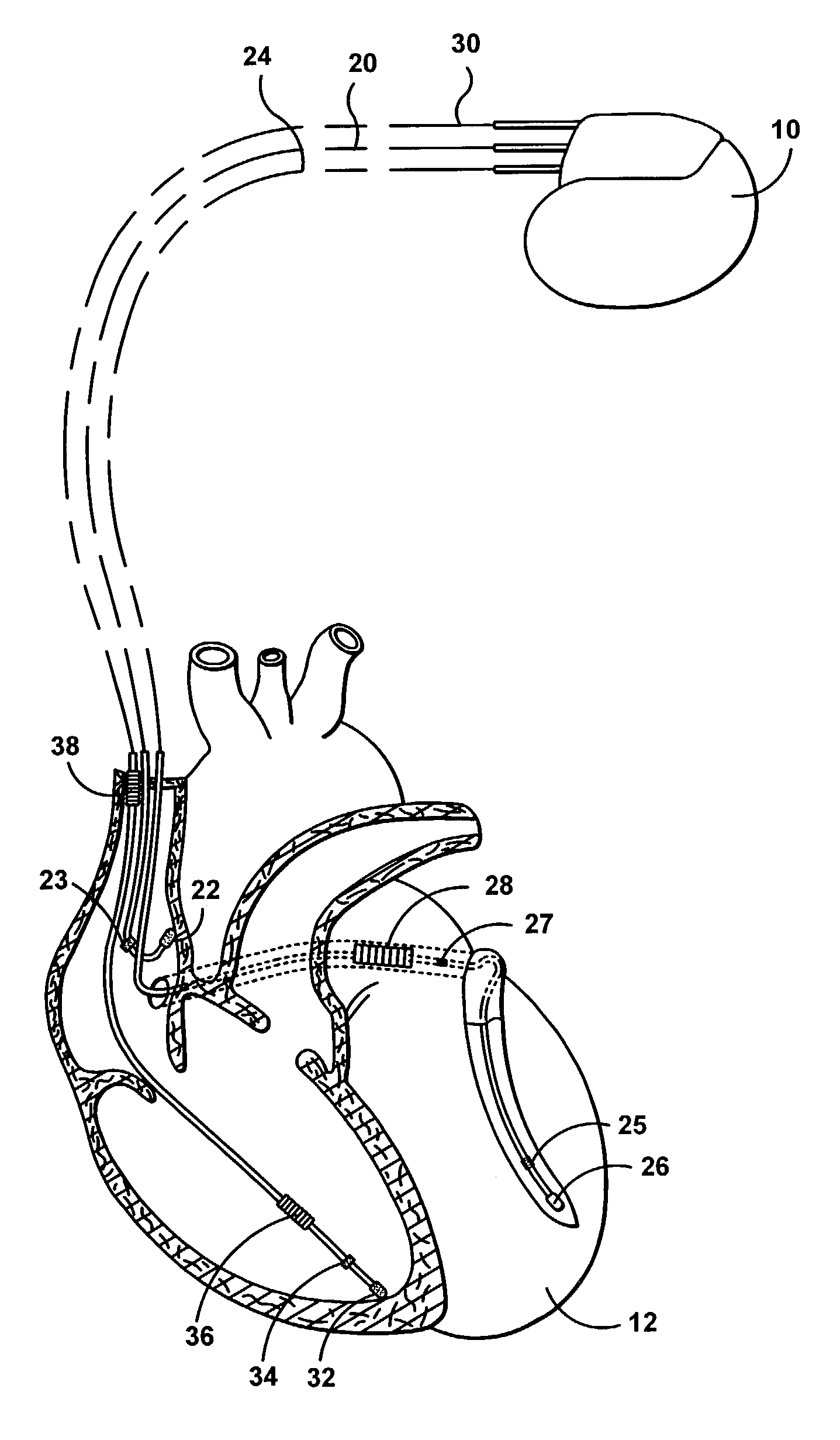
[0032]FIG. 1 illustrates a stimulation device 10 in electrical communication with a patient's heart 12 by way of three leads 20, 24 and 30 suitable for delivering multi-c...


PUM


Abstract

A leakage detection system for use in an implantable cardiac stimulation device, such as a cardioverter defibrillator. The leakage detection system includes a switch bank and a controller that regulates the switching arrangements of various switches. The leakage detection system causes pulse generators to generate a pulse-train waveform comprised of a sequence of pulses of opposite polarities, and to deliver these pulses in a preselected temporal relation. The controller detects the current leakage from the pulse generator to the tissues by sensing and analyzing the voltage or current of the pulse generator, leads, and electrodes. The pulsatility and alternating polarities of biphasic pulse-train waveforms increase the stimulation threshold of the motor or sensory nerves and excitable tissues.

Description

PRIORITY CLAIM[0001]This application claims the priority of copending U.S. provisional patent application, titled “System and Method for Imperceptible Lead Integrity Checking in an Implantable Stimulation Device,” Ser. No. 60 / 337,410, filed on Dec. 3, 2001, which is assigned to the same assignee as the present invention and which is incorporated herein by reference in its entirety.FIELD OF THE INVENTION[0002]The present invention generally relates to implantable cardiac stimulation devices. More specifically, this invention relates to an implantable cardioverter defibrillator and associated method for measuring the patient impedance. The impedance measuring system employs pulse-train waveforms for checking the integrity of various leads implanted in a patient's dysfunctional heart.BACKGROUND OF THE INVENTION[0003]In the normal human heart, the sinus node, that is generally located near the junction of the superior vena cava and the right atrium, constitutes the primary natural pacem...

Claims


Application Information

Patent Timeline
Patent Type & Authority Patents(United States)
IPC IPC(8): A61N1/36
CPCA61N1/3931A61N2001/083
Inventor MOUCHAWAR, GABRIEL A.AMELY-VELEZ, JORGE N.BADELT, STEVEN W.
Owner PACESETTER INC
Learn More