
System and method for detecting electric events in chambers of a heart

a heart and chamber technology, applied in the field of system for detecting electric cardiac events in chambers of hearts, can solve the problem that the signal-to-noise ratio is often unacceptable low, and achieve the effect of improving the signal-to-noise ratio

Inactive Publication Date: 2009-08-27
ST JUDE MEDICAL
View PDF15 Cites 3 Cited by
  • Summary
  • Abstract
  • Description
  • Claims
  • Application Information

AI Technical Summary

Benefits of technology

[0009]An object of the present invention is to solve this problem and make detection of capture and loss of capture possible in all the chambers of the heart, also of the left atrium and left ventricle without using the above-mentioned conventional unipolar sensing which often results in a too low signal-to-noise ratio as mentioned.
[0013]According to an advantageous embodiment of the system according to the invention the leads adapted for implantation in a coronary vein on the left side of the heart are unipolar. The use of unipolar left side leads involves several important advantages. Unipolar leads are thinner than bipolar leads, they are softer and more flexible at the distal end portion, have a simpler mechanical construction and a better longevity. An unipolar lead can be more easily bent distally using a pre-bent or steerable stylet which is important for making passage of sharp bends in coronary vessels possible. It is also easier to slide a unipolar lead over a sharply bent guidewire inside a coronary vein and to retract the guidewire after positioning the lead tip in a proper position. Bipolar leads, on the other hand, are often too thick for implantation in all the coronary veins which can be candidates for e.g. left ventricular stimulation and sensing. It can for instance be impossible to pass a sharp bend because the distal end of the bipolar lead is too stiff. The advantages of bipolar leads are that they normally give a higher signal-to-noise ratio, and bipolar stimulation reduces the risk of muscular stimulation at the stimulator case. Bipolar sensing can, however, sometimes be difficult when an action potential is passing both electrodes simultaneously and the signals are similar. In such a case unipolar sensing is preferred. Phrenicus stimulation also often requires attention at left ventricular pacing, since bipolar pacing on the left ventricle increases the risk of phrenicus stimulation because both the tip and the ring are involved. With this embodiment of the invention the risk of phrenicus stimulation is reduced compared to normal bipolar or unipolar stimulation which also can result in pectoral muscle stimulation when higher stimulation amplitudes are needed. In summary, with the present embodiment the physician will be more free to find an optimal location of the implanted lead on the left side of the heart, which can result in a higher phrenicus stimulation threshold, better hemodynamics and low stimulation threshold, while not losing the good properties of using bipolar leads.
[0015]According to still another advantageous embodiment of the system according to the invention the electrodes are adapted for implantation in a coronary vein on the left atrium, and in a coronary vein on the left ventricle or in the right ventricle respectively. Sensing between a tip electrode in the left atrium and a tip electrode in the left ventricle can be an attractive alternative. It is possible to distinguish between a P-wave and a R-wave from the direction of the rapid voltage change when the action potential passes the electrodes. By using an electrode in one of the ventricles as indifferent electrode when sensing P-waves in the left atrium interference of P-waves in the right atrium is avoided.

Problems solved by technology

However, when using an unipolar electrode for sensing with the stimulator or sensing apparatus case as indifferent electrode, the signal-to-noise ratio often becomes unacceptable low.

Method used


Image

  • System and method for detecting electric events in chambers of a heart
  • System and method for detecting electric events in chambers of a heart
  • System and method for detecting electric events in chambers of a heart

Examples


Embodiment Construction

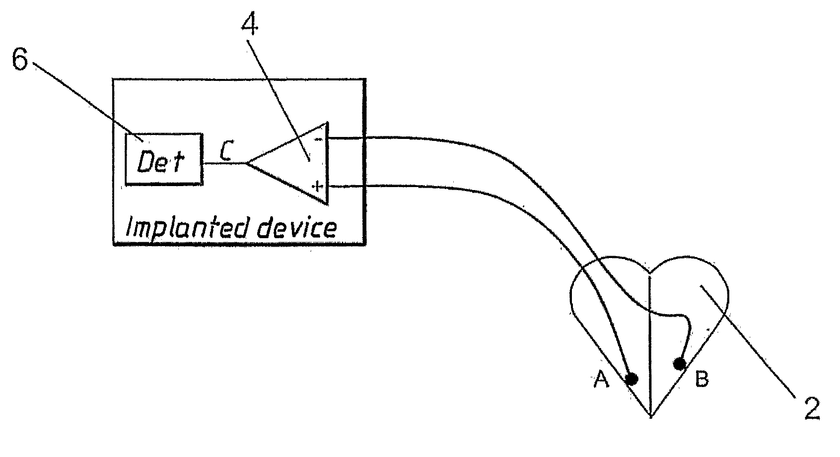
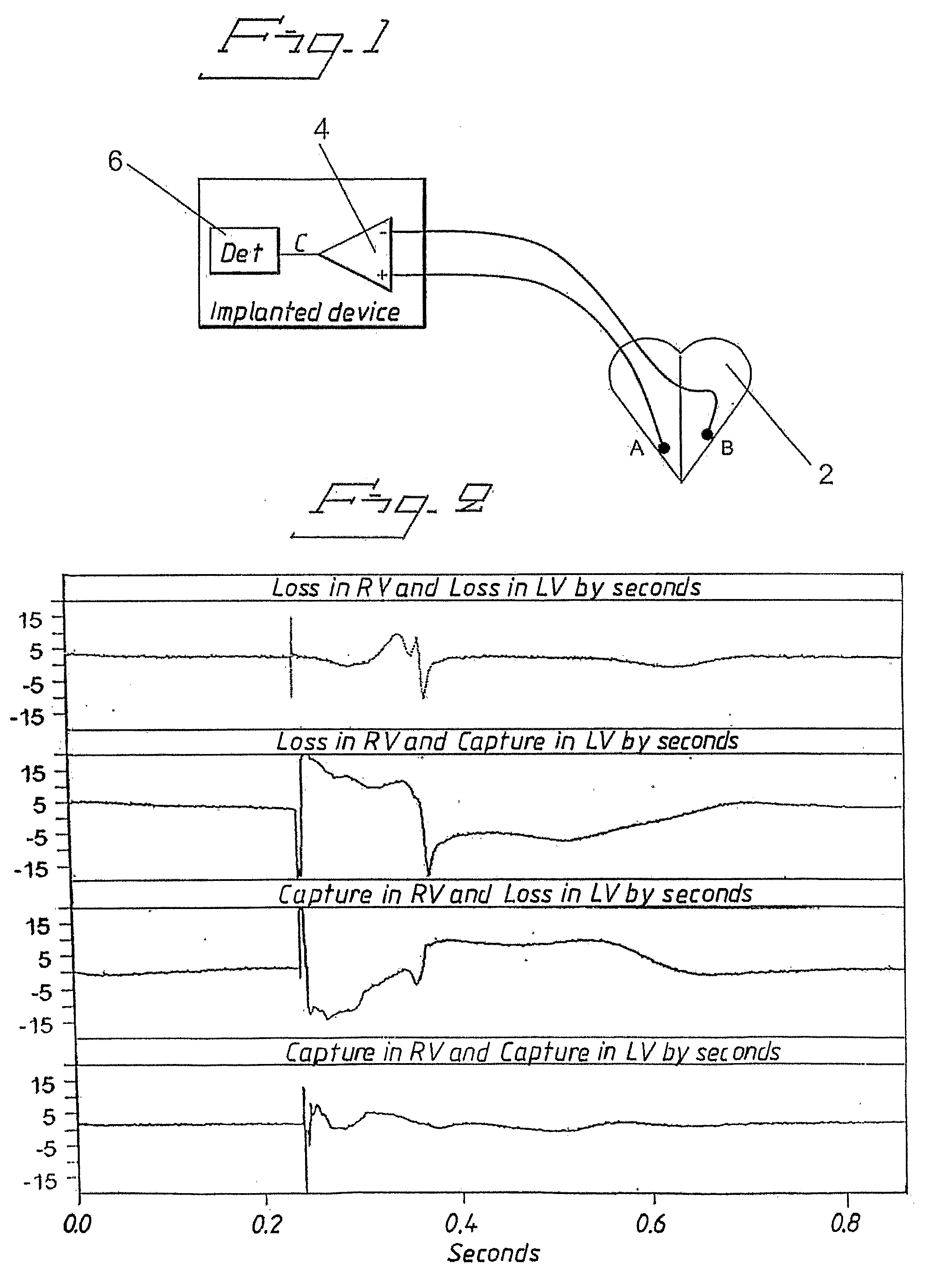
[0028]FIG. 1 shows schematically an implanted device comprising a bi-ventricular pacemaker system having bi-ventricular sensing. One electrode A is implanted in the RV of a heart 2 and another electrode B is implanted in a coronary vein on the LV. The sensed difference signal C obtained as output signal from the difference forming means 4 is supplied to an event detector 6 for determining both origin and time of electric cardiac events.

[0029]FIG. 2 shows IEGMs recorded between tip electrodes in RV and LV, cf. FIG. 1, in heart failure patients having LBBB after bi-ventricular pacing between the tip electrodes.

[0030]The curve at the bottom of FIG. 2 shows that capture in both ventricles results in a very small IEGM signal because the evoked responses practically eliminate each other since the signal amplitudes are about the same. The measured RV evoked response signal amplitude amounted to 13.1 mV and the LV evoked response signal amplitude to 14.2 mV.

[0031]The second curve from below...


PUM


Abstract

In a system and method for detecting electrical cardiac events, and a heart stimulator embodying such a system, cardiac events are detected in respective chambers of a heart by sensing electrical signals in at least two different chambers of the heart and forming a difference signal from the sensed signals, and using the difference signal to automatically distinguish between events originating from one of the chambers and events originating in another of the chambers. At least one of the sensed signals is sensed in a coronary vein on the left atrium or the left ventricle.

Description

BACKGROUND OF THE INVENTION[0001]1. Field of the Invention[0002]The present invention relates to a system for detecting electric cardiac events in chambers of a heart of the type having leads with electrodes adapted for implantation in at least two different chambers of the heart for sensing electric signals therein, and a difference former provided to supply a difference signal, formed of the signals sensed by the electrodes, to an event detector, arranged to distinguish, from the difference signal, between events originating from one of the chambers from events originating from the other one of the chambers. The invention also relates to a corresponding method and a heart stimulator embodying such a system.[0003]2. Description of the Prior Art[0004]Multi-chamber sensing system for use in e.g. multi-chamber pacing systems, need to sense electrical cardiac events, like P and R-waves, at several positions inside or outside of the heart muscle. Leads provided with one or more electrod...

Claims


Application Information

Patent Timeline
Patent Type & Authority Applications(United States)
IPC IPC(8): A61N1/368A61B5/0402
CPCA61N1/3627A61N1/368A61N1/3714A61N1/371A61N1/3684A61N1/36843
Inventor HOLMSTROM, NILSBJORLING, ANDERS
Owner ST JUDE MEDICAL
Learn More