
Photoelectrochemical air disinfection

a technology of photoelectrochemical and air disinfection, which is applied in the field of system and method of disinfection of fluids, can solve the problems of contaminated indoor environment, low level toxic chemicals, and media breeding ground, and achieve the reduction of electron-hole recombination rate and hole recombination rate involving photogenerated electrons and holes, and increase the quantum efficiency of the photocatalytic oxidation process and the destruction rate

Active Publication Date: 2006-06-20
UNIV OF FLORIDA RES FOUNDATION INC
View PDF16 Cites 34 Cited by
  • Summary
  • Abstract
  • Description
  • Claims
  • Application Information

AI Technical Summary

Benefits of technology

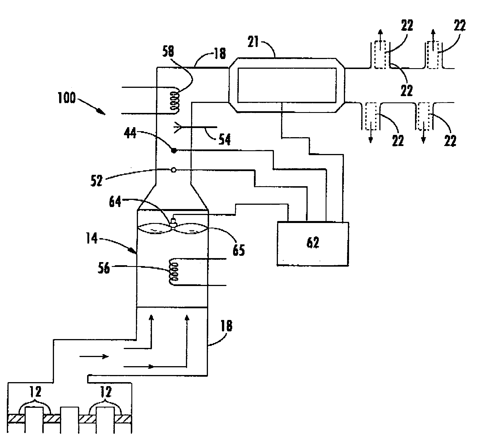
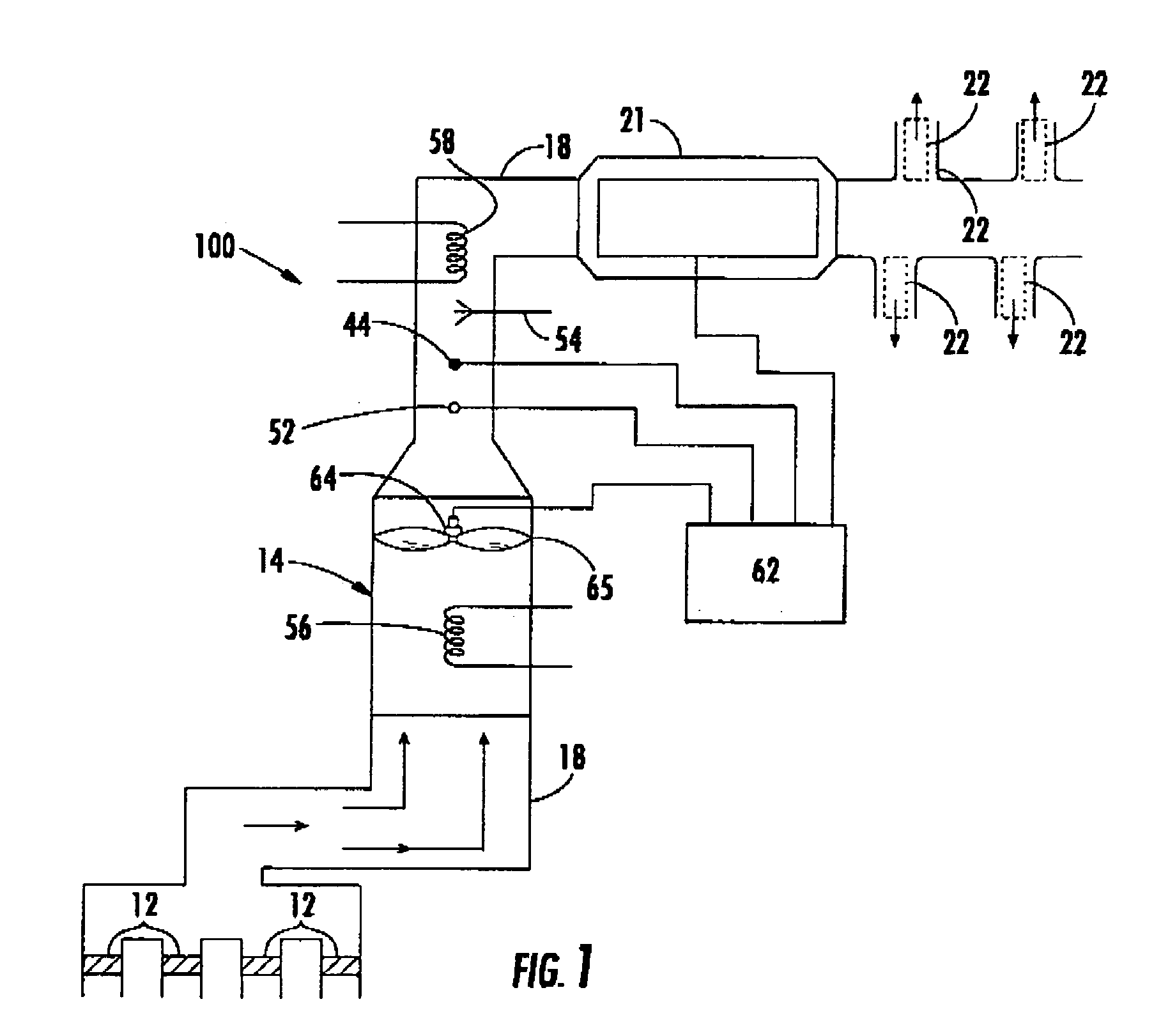
[0012]A system for disinfecting a fluid containing microorganisms or chemical contaminants includes a plurality of photocatalyst surfaces secured to a solid surface upon which a fluid to be disinfected contacts. The system can be disposed in an air supply register of a heating, ventilating and air conditioning system or in an air duct. A structure for removing a portion of the photogenerated electrons is in electrical contact with the photocatalyst layer and provides an electrically conductive path for photo generated electrons to move away from photo generated holes. As a result, the electron-hole recombination rate involving the photogenerated electrons and holes is reduced, thus increasing the quantum efficiency of the photocatalytic oxidation process and the destruction rate of microorganisms or chemical contaminants present in the fluid.
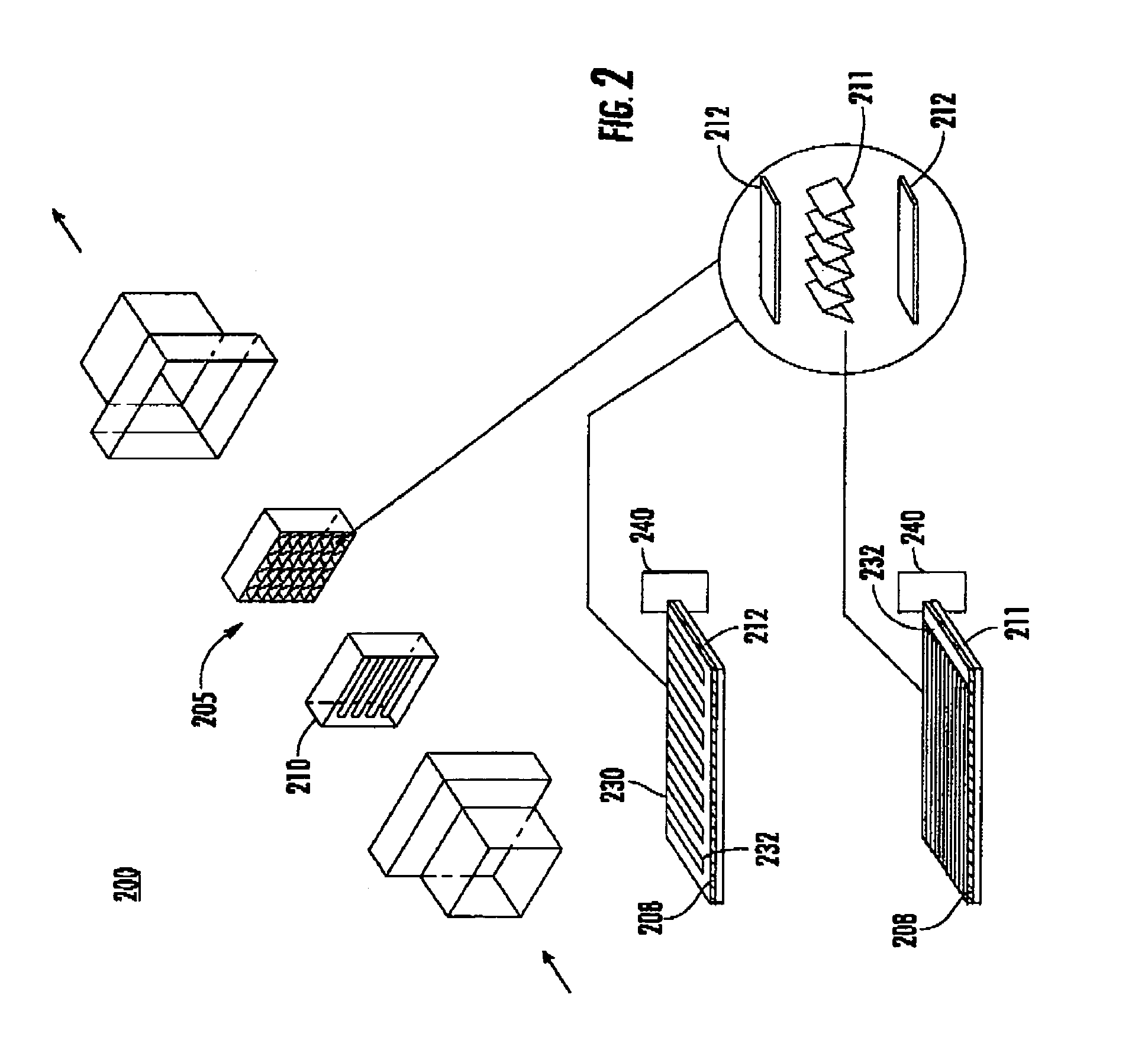
[0014]The structure for removing a portion of the photogenerated electrons can comprise an electron conducting path such as a metallic grid in contact with the photocatalyst layer, the metallic grid including a plurality of metallic strips. Gaps between the strips allow photons to reach the photocatalyst. The plurality of metal strips can be connected to an external ground. Alternatively, a source of electrical bias connected to the metal grid, the bias increasing the rate of removal of the photogenerated electrons.
[0016]A method for disinfecting fluids includes the steps of providing a photocatalyst layer comprising a plurality of photocatalyst particles, illuminating the photocatalyst layer with a source of photons having a wavelength corresponding to a band gap energy of the photocatalyst, wherein photogenerated electrons and holes are produced. A portion of the photogenerated electrons are removed, wherein a lower concentration of photogenerated electrons remain for electron-hole recombination reactions increasing removal efficiency of microorganisms or chemical contaminants from the fluid stream. The fluid stream is contacted with the photocatalyst layer, wherein at least a portion of the microorganisms or chemical contaminants in the fluid stream are photocatalytically oxidized.

Problems solved by technology

A disadvantage of such filters is that they do not permanently remove the contaminants, but just transfer them to the filter medium.
Clogging of the filter medium can result which can cause high pressure drops in addition, microorganisms trapped on the filter media continue to multiply making the filter media a breeding ground and thus hazardous.
Such UV treatment has worked well for disinfection, but the indoor environment may also be contaminated with low level toxic chemicals such as formaldehyde, styrene, and toluene.
Ultraviolet energy alone has proven generally ineffective in degrading these chemicals.
PCO reactors also feature low power consumption, potentially long service life, and low maintenance requirements.
However, even the improved methods and devices disclosed in U.S. Pat No. 5,933,702 have efficiencies which are limited by a generally slow photocatalytic oxidation process.
The slow photocatalytic oxidation process results mainly because a large percentage of photo-generated electrons recombine with photo-generated holes before the holes have a chance to participate in a photocatalytic reaction.

Method used


Image

  • Photoelectrochemical air disinfection
  • Photoelectrochemical air disinfection
  • Photoelectrochemical air disinfection

Examples


Embodiment Construction

[0026]A photocatalytic reactor-based system and related method for disinfecting fluids containing microorganisms or chemical contaminants increases the speed and efficacy of contaminant destruction significantly compared to previous systems by significantly reducing the rate of hole-electron recombination reactions. In contrast to previous advanced photocatalytic-based systems such as U.S. Pat. No. 5,933,702 which requires minimum relative humidity levels of 40% or more to achieve reasonable rates for the photocatalysis process, the present invention can operate efficiently at much lower relative humidity levels because of the reduced recombination. Effectively a larger number of active reactive sites per unit photocatalyst particle are provided by the invention. Accordingly, the invention can be used even when relative humidity is less than about 30%, while still providing substantially complete disinfection of air. Although, the invention is generally applied to air or other gases...


PUM

PropertyMeasurementUnit
band gap energyaaaaaaaaaa
humidityaaaaaaaaaa
UV wavelengthaaaaaaaaaa

Abstract

A system for disinfecting a fluid containing microorganisms or chemical contaminants includes a plurality of photocatalyst surfaces secured to a solid surface upon which a fluid to be disinfected contacts. A structure for removing a portion of the photogenerated electrons is in electrical contact with the photocatalyst layer, wherein an electron-hole recombination rate involving the photogenerated electrons and holes is reduced, thus increasing the removal rate of microorganisms or chemical contaminants from the fluid. The system can include a source of photons having a wavelength corresponding to a band gap energy of the photocatalyst to illuminate the photocatalyst layer. The invention can be used in air supply registers of a heating, ventilating and air conditioning system, or in air ducts, or used to disinfect wall coverings, floor coverings, envelopes, packages, and clothing articles.

Description

CROSS-REFERENCE TO RELATED APPLICATIONS[0001]Not applicable.STATEMENT REGARDING FEDERALLY SPONSORED RESEARCH OR DEVELOPMENT[0002]Not applicable.FIELD OF THE INVENTION[0003]The invention relates to systems and methods for disinfecting fluids using photoelectrochemical processes enhanced by electron shunting.BACKGROUND[0004]Several microbiological particle control systems exist. Mechanical and electrostatic filters can be used to reduce indoor concentrations of respirable particles, such as in a forced air heating / cooling system of a building. Microbiological filters have been used for disinfection of air and other gases because of their low cost and ease of handling. These filters can be constructed to remove not only microorganisms, but also submicron particles as well. For efficient and economic operation of these filters, the aerosol content of the air to be filtered must be low, where the term “aerosols” generally refers to microorganisms, particles, and droplets of liquid disper...

Claims


Application Information

Patent Timeline
Patent Type & Authority Patents(United States)
IPC IPC(8): B01J19/08A61L2/02A61L2/08A61L9/00A61L9/18B01D53/88F24F3/16
CPCA61L2/02A61L2/088A61L9/00A61L9/18F24F3/166B01D53/885F24F2003/1667B01D2255/802B64D2013/0651F24F8/22F24F8/192Y02A50/20
Inventor GOSWAMI, DHARENDRA YOGI
Owner UNIV OF FLORIDA RES FOUNDATION INC
Learn More