Cutting tool

a cutting tool and cutting edge technology, applied in the field of cutting tools, can solve the problems of metal removal, inability to advance in this range of operation, and adjustment of the cutting edge, and achieve the effect of high quality standards

Inactive Publication Date: 2006-06-13
HARTMETALL WERKZEUGFAB PAUL HORN
View PDF20 Cites 4 Cited by
  • Summary
  • Abstract
  • Description
  • Claims
  • Application Information

AI Technical Summary

Benefits of technology

[0006]Objects of the present invention are to provide an improved cutting tool for the purpose of making it possible, while retaining the advantages of this tool, to machine drill holes of extremely small diameters, such as ones appreciably smaller than 1 mm, while maintaining high quality standards.
[0007]According to the present invention, a high degree of reinforcement is achieved for the neck component of the cutting tool. Also, the cutting component with cutting edge mounted on its free end is achieved in that, the retaining component has, extending transversely to the plane of the cutting edge, two reinforcing components such as reinforcing ribs. The reinforcing ribs taper as they converge in the direction of the cutting component. The reinforcing compounds are positioned diametrically opposite each other in relation to the retaining component, and assume their greatest width at the point of their transition to the shank component. In the case of a conventionally designed retainer, the reinforcing ribs of the cutting component permit sure absorption of the machining forces introduced into the cutting component by the retaining component into the shank component and then into the holding component to be associated with the machine. In particular, the reinforcing ribs counter vibrations occurring during machining with the cutting component, and retain the cutting component precisely in its required machining plane. Since the reinforcing ribs extend perpendicular to the plane of the cutting component with its cutting edge, they occupy little structural space. Because of their convergent configuration, the ribs permit engagement of the cutting components even in drill holes of small diameter.
[0008]In that the reinforcing ribs preferably are obtained from the neck component by a grinding process from the neck component and always have two different grinding patterns with different, preferably concave, radii of curvature in the direction of the cutting component, very high supporting forces can be achieved for the cutting component. The structural space required for the reinforcing ribs is optimized as well, so that a high degree of stiffening is achieved with geometrically small reinforcing ribs, which thus permit engagement of the cutting component also in drill holes for a machining process whose diameter is smaller than 1 mm, and 0.7 mm in particular.

Problems solved by technology

Spacing the cutting edge away from the diametral advance plane results in clearance angles which may lead to unfavorable results in metal removal, such as vibration of the tool.
Despite the advantageous tool holding, the integrated configuration of the tool, and its construction by use of cutting alloy materials, these disclosed measures do not make it possible to advance in this range of operation with boring diameters smaller than 1 mm to achieve the machining qualities desired.
Because of the flat application of the plate with three cutting edges on the end of the holder and the disclosed possibility of fastening by means of a screw connection, misadjustment of the machining edge may occur, and the configuration of the disclosed solution is so large that application of this for drill holes of extremely small diameter is not possible.

Method used


Image

  • Cutting tool
  • Cutting tool
  • Cutting tool

Examples


Embodiment Construction

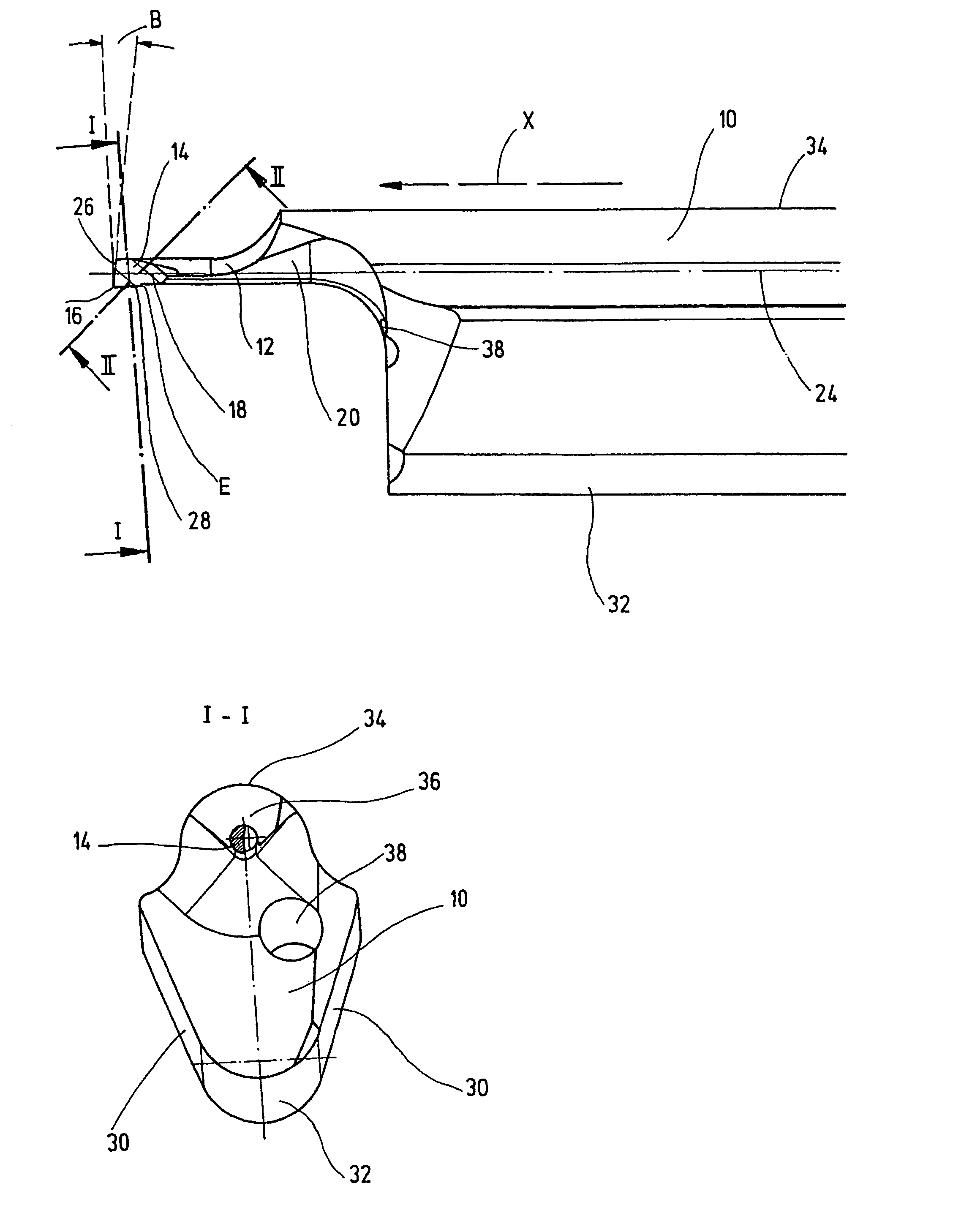
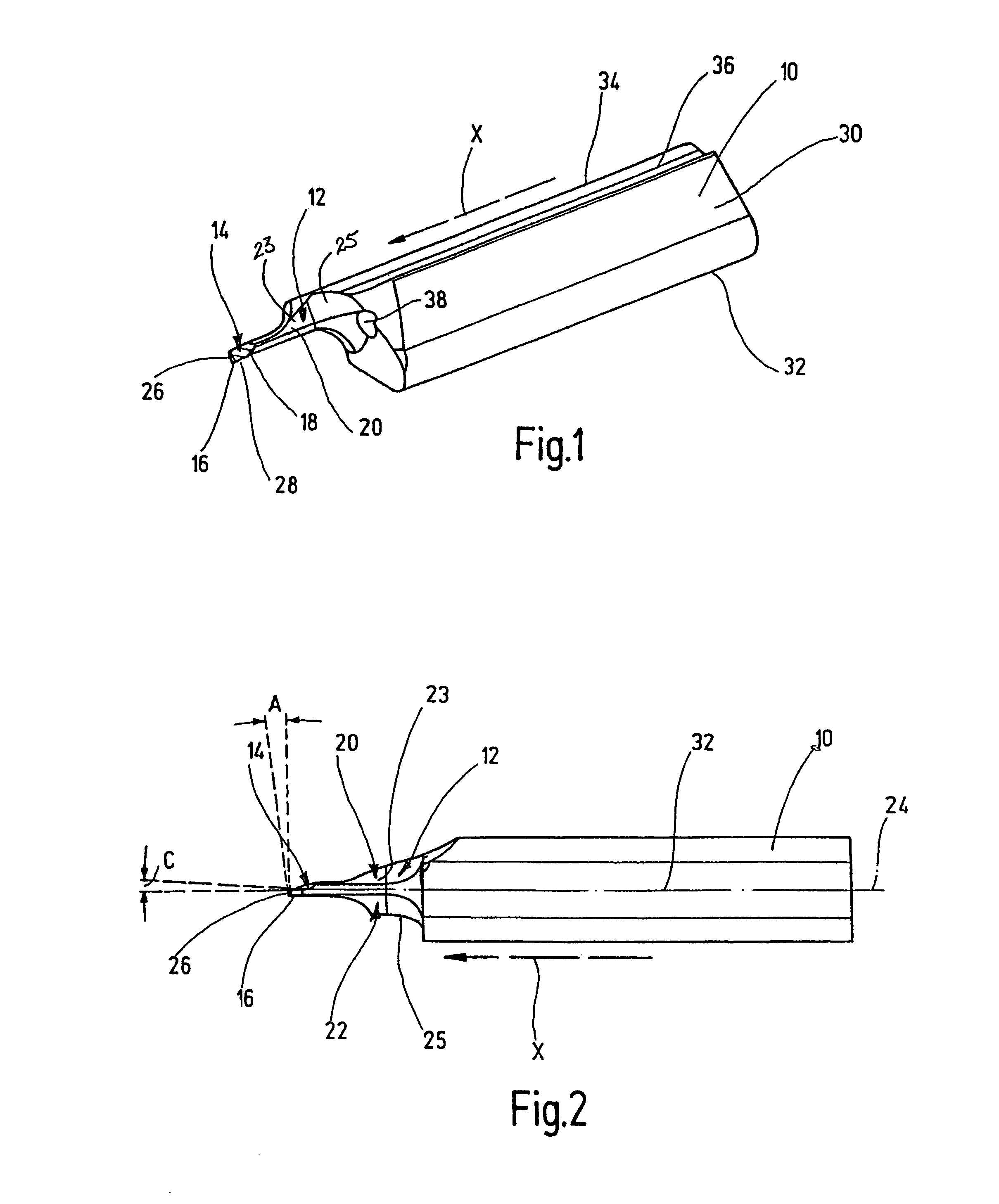
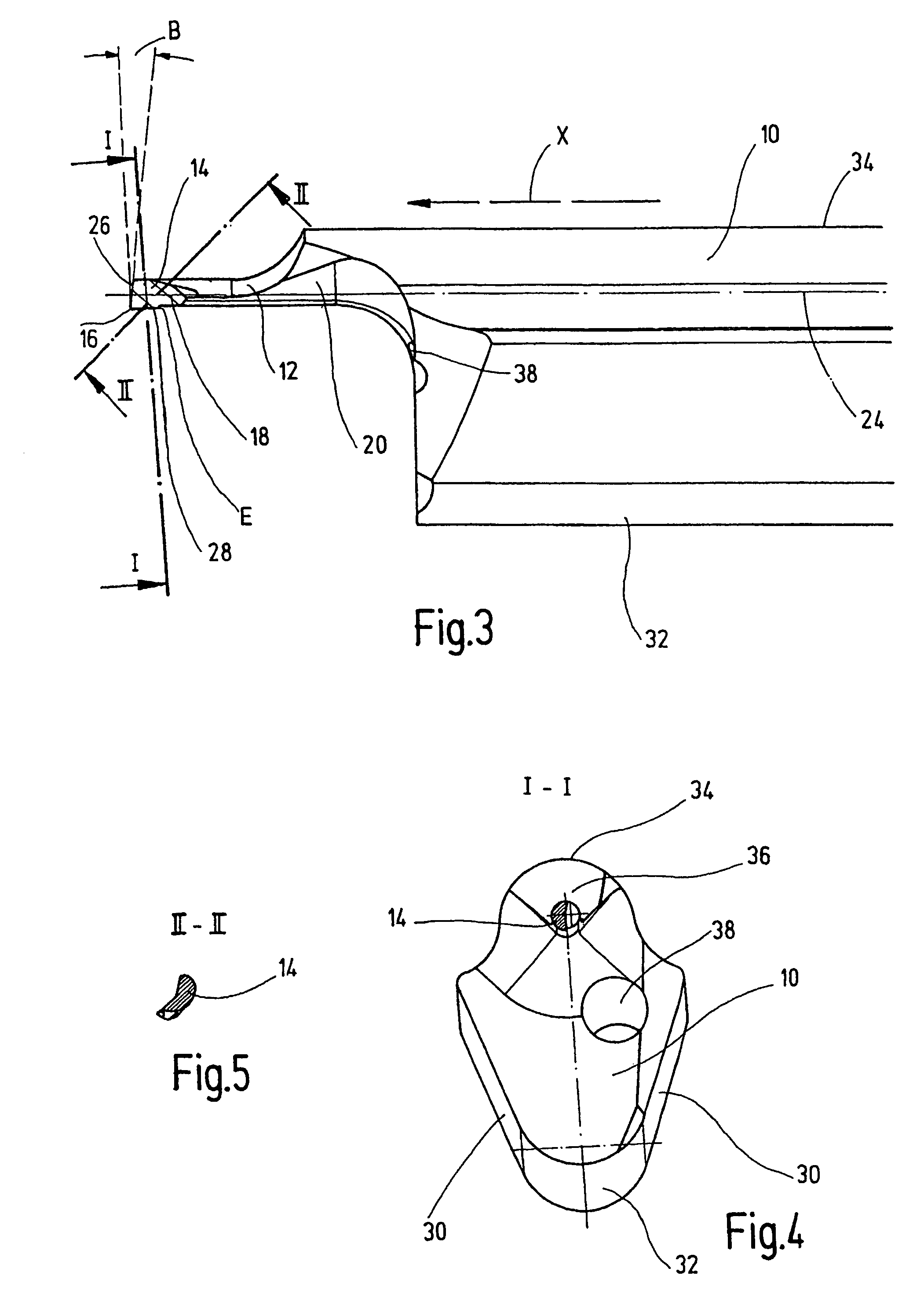
[0016]The cutting tool illustrated in the figures is used in particular for hollowing drill holes having a bore diameter less than 1 mm, preferably in the area of 0.7 mm. The cutting tool has a clamping component 10 for securing the tool in tool holder not shown. Use may be made, for example, of the tool holders as described in European Patent 0 385 280 issued to the applicant. The side of the clamping component 10 facing away from the tool holder is adjoined by a neck component 12 tapered in relation to the clamping component 10. The neck component 12 has integral with it, on its free end a cutting component 14 provided at its extremity with a cutting edge 16. Cutting edge 16 adjoins a face 18 of the cutting component 14 in the direction of the neck component 12. The direction of machining with the tool is indicated in FIGS. 1 to 3 by an arrow identified by an “X.”

[0017]As seen in FIG. 2 in particular, the neck component 12 has, extending along it transversely to the plane with the...


PUM

PropertyMeasurementUnit
Angleaaaaaaaaaa
Angleaaaaaaaaaa
Angleaaaaaaaaaa

Abstract

A cutting tool, in particular for the turning out of drillings, has a clamping piece (10) for fixing the tool in a clamp holder. The clamping piece (10) includes two clamping surfaces (30), which converge on each other in the direction of the one side (32) of the clamping piece (10). In the direction of the other side (34) of the clamping piece (10), the clamping surfaces extend into a roof-type surface (36). On the side of the clamping piece (10) facing away from the clamp holder, the clamping surfaces connect to a rod-like neck piece (12), which tapers in cross-section relative to the clamping piece (10). The free end of the clamping piece is connected to a cutting piece (14) as one piece, and is provided with a cutting edge (16) on the external end thereof to which a face (18) of the cutting piece (14) connects in the direction of the neck piece (12). A high degree of reinforcement for the neck piece and the cutting piece arranged on its free end with its blade or the blade edge is achieved. The neck piece (12) has two reinforcement pieces running along it, transverse to the plane of the cutting edge (16). The reinforcement pieces are reinforcing ribs (20, 22) which convergently taper in the direction of the cutting piece (14), are diametrically opposed in relation to the neck piece (12) and have their greatest width at the point of transition into the clamping piece (10).

Description

FIELD OF THE INVENTION[0001]The present invention relates to a cutting tool, in particular for hollowing drill holes, having a clamp component for securing the tool in a tool holder. A neck component is tapered in cross section relative to the clamp component adjoining on the side of the clamp component facing away from the tool holder. An integral cutting component is provided at its extremity with a cutting edge which adjoins a face of the cutting component in the direction of the neck component. An inner cutter for machining the interior surface of drill holes is provided, for example, for cutting circumferential grooves into the drill hole wall, for precision machining of the drill hole wall by finish turning of the drill hole wall, for thread cutting in a bore hole, and the like.BACKGROUND OF THE INVENTION[0002]A comparable cutting tool is disclosed in EP-B-0 385 280. The cutting edge of the tool moves in a radial direction of advance during parting in machining the interior wa...

Claims


Application Information

Patent Timeline
IPC IPC(8): B23B29/04B23B27/00B23B29/02
CPCB23B27/007B23B29/022B23B2222/28Y10T407/25B23B2270/20B23B2270/60Y10T407/14B23B2250/12
Inventor OETTLE, MATTHIAS
Owner HARTMETALL WERKZEUGFAB PAUL HORN
Why Eureka
Try Eureka