
Internal combustion engine fuel supply system

a fuel supply system and internal combustion engine technology, applied in the direction of machines/engines, separation processes, mechanical equipment, etc., to achieve the effect of reducing the nox content of engine exhaus

Inactive Publication Date: 2006-05-30
NUCELLSYS GMBH
View PDF15 Cites 11 Cited by
  • Summary
  • Abstract
  • Description
  • Claims
  • Application Information

AI Technical Summary

Benefits of technology

[0007]The present system includes a hydrogen generator to produce a hydrogen-rich fuel for combustion in an internal combustion engine. The hydrogen-rich fuel may also be used in a downstream DeNOx catalytic converter to reduce the NOx content of the engine exhaust. Heat is recovered from the exhaust stream and supplied to the hydrogen generator to support the endothermic conversion of raw fuel to the hydrogen-rich fuel.
[0008]Using endothermic reactions during the production of hydrogen-rich fuel increases the calorific value of the reactants by the amount of energy recovered from the engine exhaust. This leads to a correspondingly higher overall efficiency of the whole system, which goes hand in hand with a reduction in carbon monoxide emissions.
[0009]Hydrogen-rich fuel produced by endothermic steam reforming in addition to being suitable for combustion in the internal combustion engine, is particularly useful as a reducing agent in a DeNOx catalytic converter. The increased nitrogen output, which in the case of methanol—due to the high purity of the fuel—predominantly consists of thermal nitrogen oxides, can be reduced by a DeNOx catalytic converter in combination with the use of the produced hydrogen-rich fuel as a reducing agent. This makes it possible to increase the combustion temperature, and thus the efficiency, of the internal combustion engine.

Problems solved by technology

For conversion of hydrocarbon fuels, similar amounts of energy have to be transferred at significantly higher temperatures, so that the energy content and the temperature level are potentially only sufficient to partially convert the fuel.

Method used


Image

  • Internal combustion engine fuel supply system
  • Internal combustion engine fuel supply system

Examples


Embodiment Construction

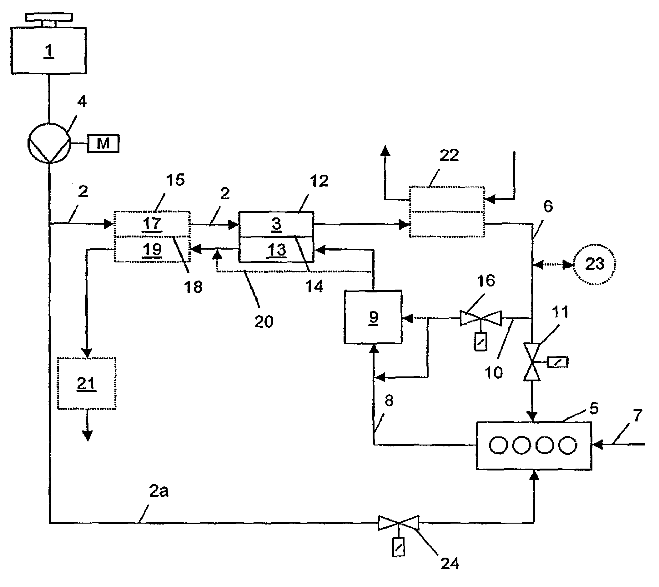
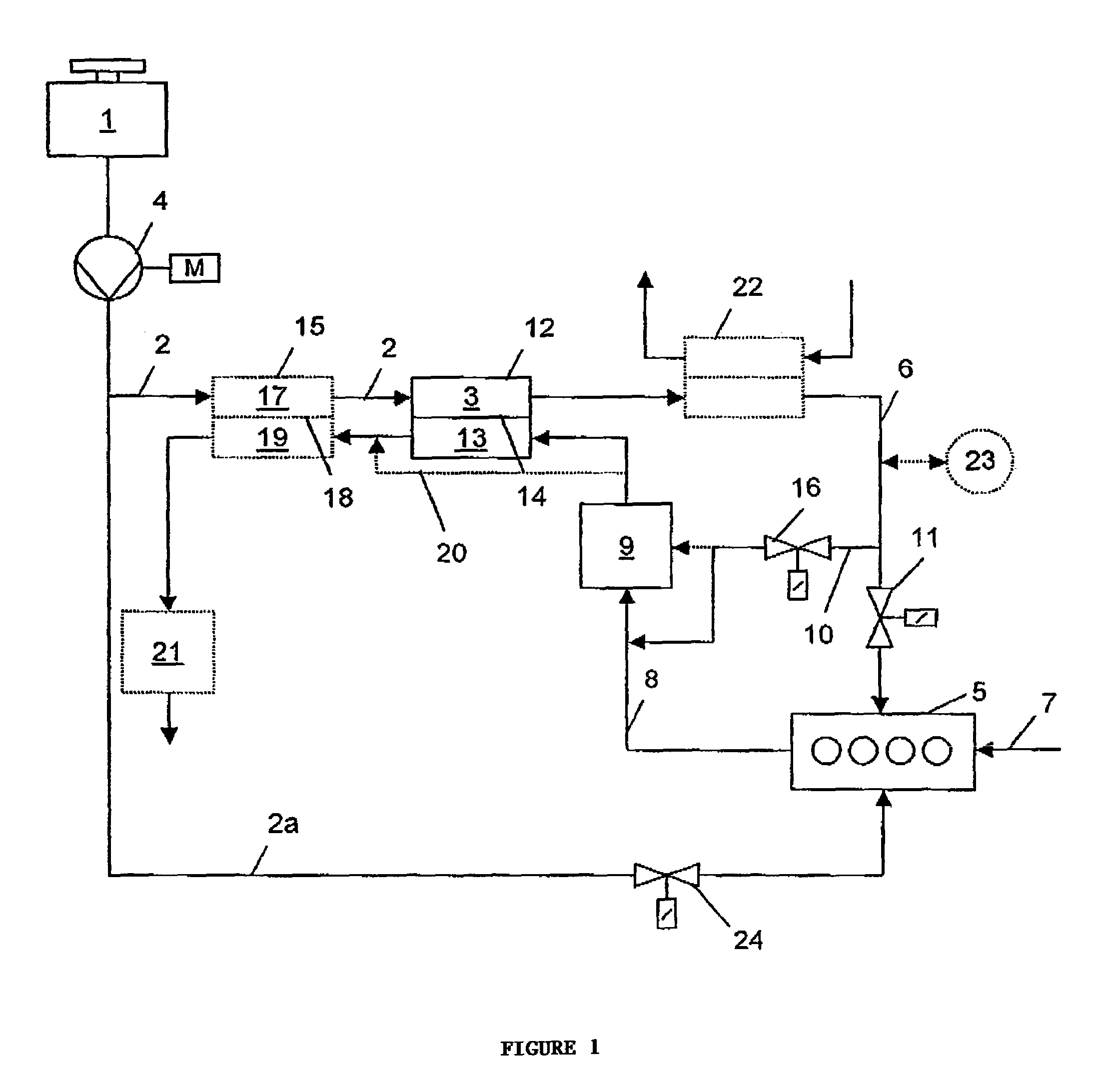
[0017]Raw fuel, preferably in liquid form, is carried in a vehicle in a tank 1, and is fed to a hydrogen generator 3 (e.g. a reformer) by a raw fuel feed line 2. Raw fuel feed line 2 contains a pump 4, which pumps and possibly meters the raw fuel. In hydrogen generator 3, an endothermic reaction converts the raw fuel into a gaseous hydrogen-rich fuel, which is then supplied to an internal combustion engine 5 through a hydrogen-rich fuel feed line 6. To regulate the amount of hydrogen-rich fuel supplied, the hydrogen-rich fuel feed line is equipped with a first valve 11. Air required for combustion is supplied to internal combustion engine 5 through an intake line 7. After combustion, the exhaust is discharged through an exhaust line 8.

[0018]Exhaust line 8 contains an exhaust purification system 9, preferably a DeNOx catalytic converter, in which nitrogen oxides contained in the exhaust are reduced to nitrogen using reducing agents present in the exhaust.

[0019]To supply or to increas...


PUM


Abstract

A system to supply hydrogen-rich fuel to an internal combustion engine, whereby a hydrogen-rich gas is produced from a liquid raw fuel by a hydrogen generator. The exhaust line of the internal combustion engine contains an exhaust purification system, such as a DeNOx catalytic converter, which is at least temporarily supplied with hydrogen-rich gas through a bypass line. In addition, the exhaust line is in thermal contact with the hydrogen generator in order to recover thermal energy.

Description

CROSS-REFERENCES TO RELATED APPLICATIONS[0001]This application is a continuation of U.S. patent application Ser. No. 10 / 484,458, filed Jan. 21, 2005, now abandoned, which is a U.S. National Stage application of PCT / EP02 / 08098 filed Jul. 19, 2002, which claims priority to German Application No. 101 35 643.9, filed Jul. 21, 2001; all of these applications are incorporated herein by reference in their entireties.FIELD OF THE INVENTION[0002]The invention concerns a system for supplying fuel to an internal combustion engine.DESCRIPTION OF THE RELATED ART[0003]A goal in the development of motor vehicles with internal combustion engines today is the reduction of fuel consumption and carbon dioxide emissions. It is also desired to reduce other pollutants in the exhaust, in particular nitrogen oxides (NOx).[0004]Motor vehicles with cracking carburetors, in which hydrocarbon fuels are converted by a partial oxidation device prior to entering the internal combustion engine, are well known. How...

Claims


Application Information

Patent Timeline
Patent Type & Authority Patents(United States)
IPC IPC(8): F01N3/00B01D53/94F01N3/20F02B51/02
CPCB01D53/9431F01N3/2066F01N2610/03F01N2610/04F02B2201/064Y02A50/20Y02T10/12
Inventor BENZ, UWEDIETRICH, GUENTHERZUR MEGEDE, DETLEF
Owner NUCELLSYS GMBH
Learn More