
Fuse link trim algorithm for minimum residual

a technology of fuse link and residual, applied in the direction of digital storage, instruments, transmission systems, etc., can solve the problems of increasing circuit noise and power consumption, reducing circuit performance, etc., and achieve the effect of reducing thermal drift, power supply drift, circuit noise and/or power consumption of differential input stages

Active Publication Date: 2006-05-23
TEXAS INSTR INC
View PDF4 Cites 9 Cited by
  • Summary
  • Abstract
  • Description
  • Claims
  • Application Information

AI Technical Summary

Benefits of technology

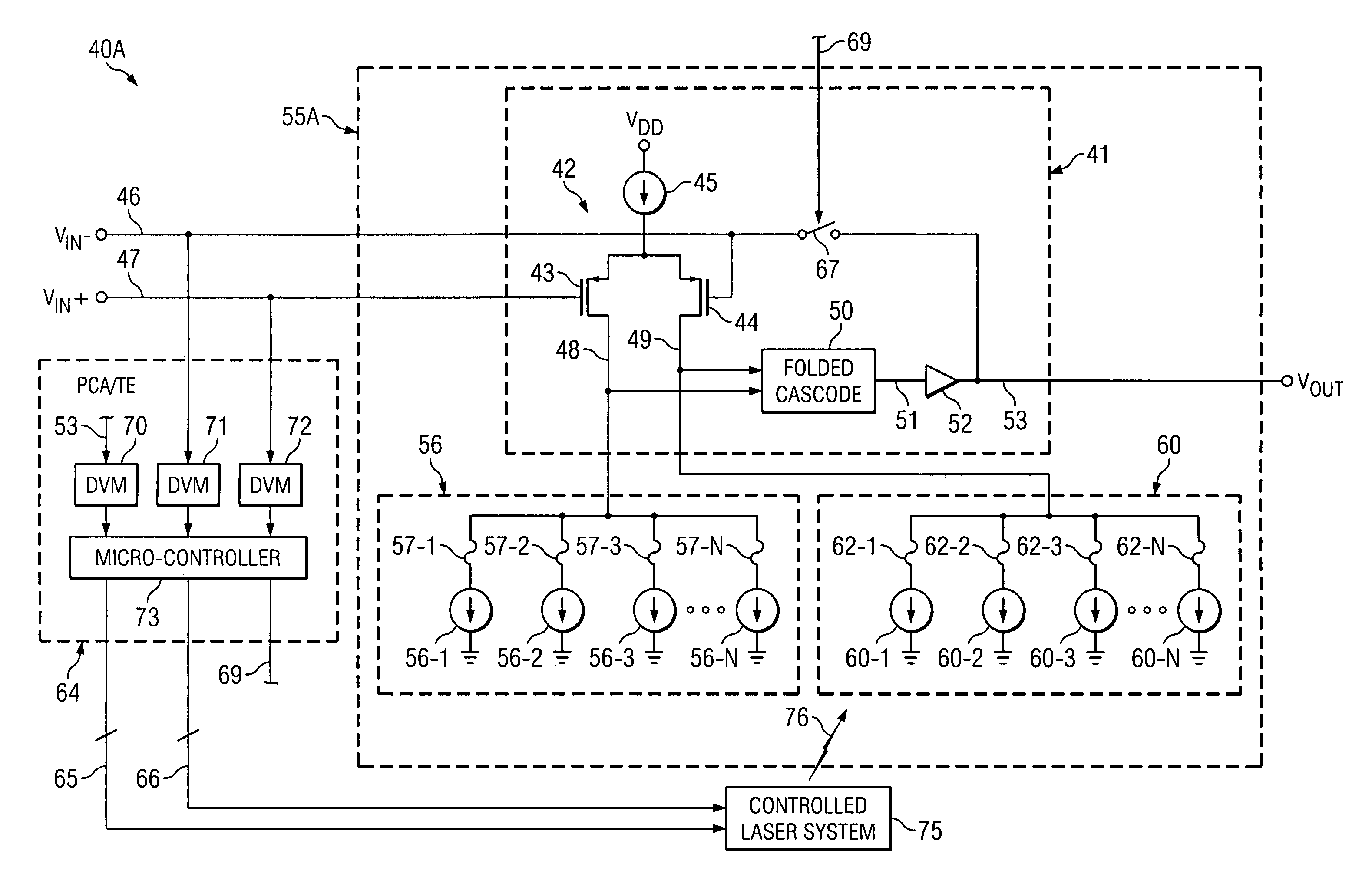
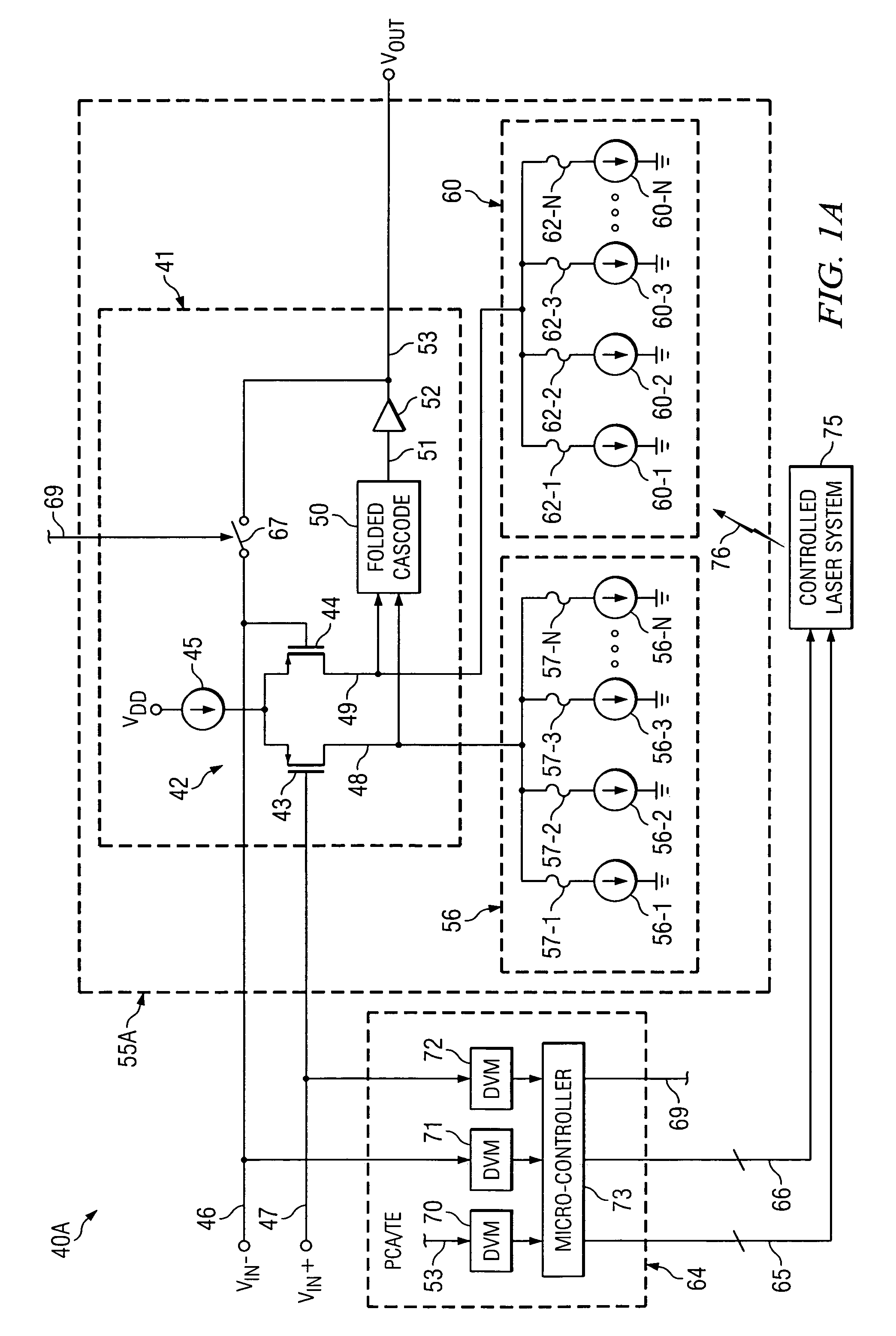
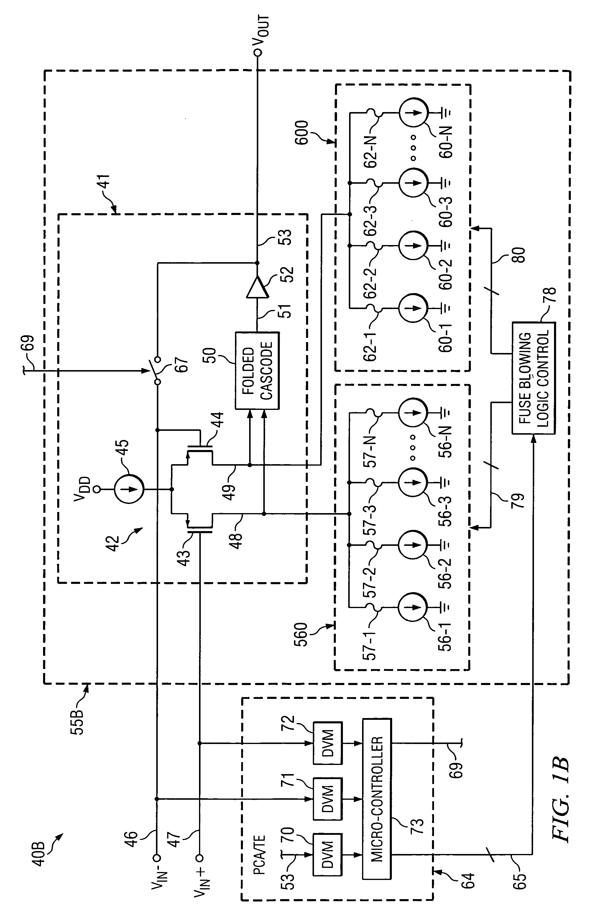
The present invention provides an improved differential trimming technique that reduces input offset voltages associated with a differential input stage and also reduces thermal drift, power supply drift, circuit noise, and power consumption of the differential input stage. The technique includes measuring an initial value of a parameter and determining whether the parameter exceeds a predetermined reference value. If the parameter exceeds the reference value, the technique involves iteratively blowing fuses of a trim array to decrease the parameter by weighted amounts corresponding to the bit number values of the trim array. The technique also includes measuring an initial value of the parameter and determining whether the parameter exceeds a second accuracy value to decrease the parameter to a value less than the first accuracy value. The integrated circuit includes an operational amplifier and the parameter is an input offset voltage of the operational amplifier. The technique reduces the number of residual trim elements and improves the accuracy of the integrated circuit.

Problems solved by technology

This is because the presence of residual links and corresponding residual trim currents can diminish circuit performance.
The presence of the residual trim elements and corresponding residual trim currents is undesirable because it makes the circuit more susceptible to thermal drift and power supply drift, and may also increase circuit noise and power consumption.

Method used


Image

  • Fuse link trim algorithm for minimum residual
  • Fuse link trim algorithm for minimum residual
  • Fuse link trim algorithm for minimum residual

Examples


Embodiment Construction

[0021]The method and structure of the present invention are utilized to selectively control blowing of fuses or laser-cutting of links in binarily weighted current sources, in order to trim a circuit parameter, such as an input offset voltage, wherein one trim array is connected to a (+) side of a differential input transistor pair of an integrated circuit chip and the other trim array is connected to a (−) side of the input transistor pair. The trimming is performed according to a trimming algorithm to essentially eliminate the above mentioned residual trim elements and associated residual trim currents so that the only trim elements that remain connected to the differential input transistor pair are those necessary to reduce its offset voltage to an acceptable value. This has the effect of making the differential input transistor stage less susceptible to thermal drift, power supply drift, circuit noise, and / or power consumption.

[0022]Referring to FIG. 1A, a system 40A includes pr...


PUM


Abstract

A parameter of an integrated circuit including a first trim array and a second trim array is trimmed by measuring an initial value of the parameter, determining whether the parameter exceeds a reference value, and as long as the parameter exceeds the reference value, repetitively blowing fuses associated with binarily weighted trim elements of the first trim array to eliminate trim contributions thereof to thereby decrease the parameter by weighted amounts corresponding to a present trim array bit number value until either all fuses of the first trim array have been blown or enough have been blown to cause the parameter to be less than a −LSB / 2 weight. If the parameter then is less than the −LSB / 2 weight, a fuse of the second trim array corresponding to a present bit number is blown to increase the parameter to greater than a +LSB / 2 weight. The procedure is repeated until all fuses in one trim array have been blown, to thereby minimize the number of residual trim elements.

Description

BACKGROUND OF THE INVENTION[0001]The present invention relates generally to systems and techniques for trimming a parameter such as input offset voltage of an amplifier to a particular target value by blowing / cutting fuse links, and more particularly to systems and techniques for avoiding the presence of “residual” un-blown or un-cut fuse links after the trimming process is complete. This is because the presence of residual links and corresponding residual trim currents can diminish circuit performance.[0002]The invention also relates to avoiding the need for a-priori knowledge of “trim step” sizes before successful trimming can be initiated. For example, if an operational amplifier is to be trimmed so as to have a particular input offset voltage wherein a differential input transistor pair has a particular transconductance, that results in a particular output current of the differential input transistor pair being applied as input to a folded cascode stage. The junction point or co...

Claims


Application Information

Patent Timeline
Patent Type & Authority Patents(United States)
IPC IPC(8): H03M1/10
CPCG11C7/06G11C17/16G11C17/165G11C17/18G11C29/027G11C29/028G11C29/50008G11C29/02G11C2207/2254
Inventor JONES, MARK A.
Owner TEXAS INSTR INC
Learn More