
ptat current source circuit

A current source and circuit technology, applied in the direction of regulating electrical variables, instruments, control/regulating systems, etc., can solve the problems of complex circuit structure and unsatisfactory consistency, achieve simple and effective circuits, improve consistency and power supply rejection ratio, Low power consumption

Active Publication Date: 2021-06-18
SHANGHAI SHENXILING MICROELECTRONICS TECH CO LTD
View PDF6 Cites 0 Cited by
  • Summary
  • Abstract
  • Description
  • Claims
  • Application Information

AI Technical Summary

Problems solved by technology

Its circuit structure is still relatively complex, and its consistency cannot meet the current needs

Method used


Image

  • ptat current source circuit
  • ptat current source circuit
  • ptat current source circuit

Examples


Embodiment Construction

[0040] The present invention will be described in detail below in conjunction with specific embodiments. The following examples will help those skilled in the art to further understand the present invention, but do not limit the present invention in any form. It should be noted that those skilled in the art can make several changes and improvements without departing from the concept of the present invention. These all belong to the protection scope of the present invention.

[0041] The invention designs a precise PTAT current source integrated circuit. Divide the forward voltage difference of the triode PN junction or diode PN junction with different current densities by a resistance to obtain a current, which mirrors the required current source. If the temperature characteristic of the resistance is very small, the current source is related to the absolute temperature. Proportional to PTAP current (ProportionalTo Absolute Temperature). Using this current source to flow th...


PUM


Abstract

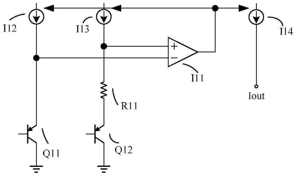
The present invention provides a PTAT current source circuit, comprising: an error operational amplifier; a first transistor including a first PN junction, and a P-type region of the first PN junction is connected to a first current source and an inverter of the error operational amplifier a phase terminal; a second transistor, including a second PN junction, the P-type region of the second PN junction is connected to the second current source and the non-inverting terminal of the error operational amplifier through a series resistor; wherein, the error operational amplifier The output terminal is connected to the first current source, the second current source and the output current source, and is used to control the first current source, the second current source and the output current source, and the output current source has The output is the output of the PTAT current source circuit. The circuit of the invention is simple and effective, the layout area is small, the cost is low, the power consumption is small, and the offset voltage and area of ​​the error operational amplifier are greatly reduced.

Description

technical field [0001] The invention relates to the field of electronic circuits, in particular to a PTAT current source circuit. Background technique [0002] Bias circuits with high precision, high consistency and high power supply rejection ratio are required in many circuits requiring high precision, especially in temperature sensors, which directly determine the consistency and accuracy of the sensor. This high consistency and high power supply rejection ratio current source or voltage becomes the decisive factor of sensor performance. [0003] Patent document CN 107992142A discloses a high power supply rejection ratio reference current source in the field of analog integrated circuits. The reference current source has a start-up circuit, a reference unit and a feedback circuit, including a control terminal, a power supply terminal, a reference supply terminal and a ground terminal. The control terminal receives the control signal VCON, its power supply terminal is cou...

Claims


Application Information

Patent Timeline
Patent Type & Authority Patents(China)
IPC IPC(8): G05F1/567
CPCG05F1/567
Inventor 谢芳
Owner SHANGHAI SHENXILING MICROELECTRONICS TECH CO LTD
Learn More