
Method for fabricating carbon nanotube yarn

a carbon nanotube and yarn technology, applied in the direction of catalyst activation/preparation, physical/chemical process catalysts, metal/metal-oxide/metal-hydroxide catalysts, etc., can solve the problems of limiting the application of carbon nanotubes, short lengths are not suitable for macroscopic objects, and all carbon nanotubes produced by these methods are short in length

Active Publication Date: 2006-05-16
HON HAI PRECISION IND CO LTD +1
View PDF5 Cites 464 Cited by
  • Summary
  • Abstract
  • Description
  • Claims
  • Application Information

AI Technical Summary

Benefits of technology

The present invention provides a method for making long carbon nanotube structures, specifically carbon nanotube yarn. The method involves forming a carbon nanotube array by depositing a catalyst on a substrate and controlling the temperature and gas mixture to grow carbon nanotubes on the substrate. The carbon nanotube array is then drawn out to create a carbon nanotube yarn. The technical effect of this invention is the ability to make long carbon nanotube structures with improved strength and flexibility.

Problems solved by technology

However, all carbon nanotubes which have been produced by these methods are short in length, the longest carbon nanotubes being only several-hundred micrometers in length.
These short lengths restrict the applications of carbon nanotubes.
In particular, such short lengths are not suitable for use in macroscopic objects, such as bullet proof vests and fabrics that block electromagnetic waves.

Method used


Image

  • Method for fabricating carbon nanotube yarn
  • Method for fabricating carbon nanotube yarn

Examples


Embodiment Construction

[0020]A method for creating a carbon nanotube yarn comprises:

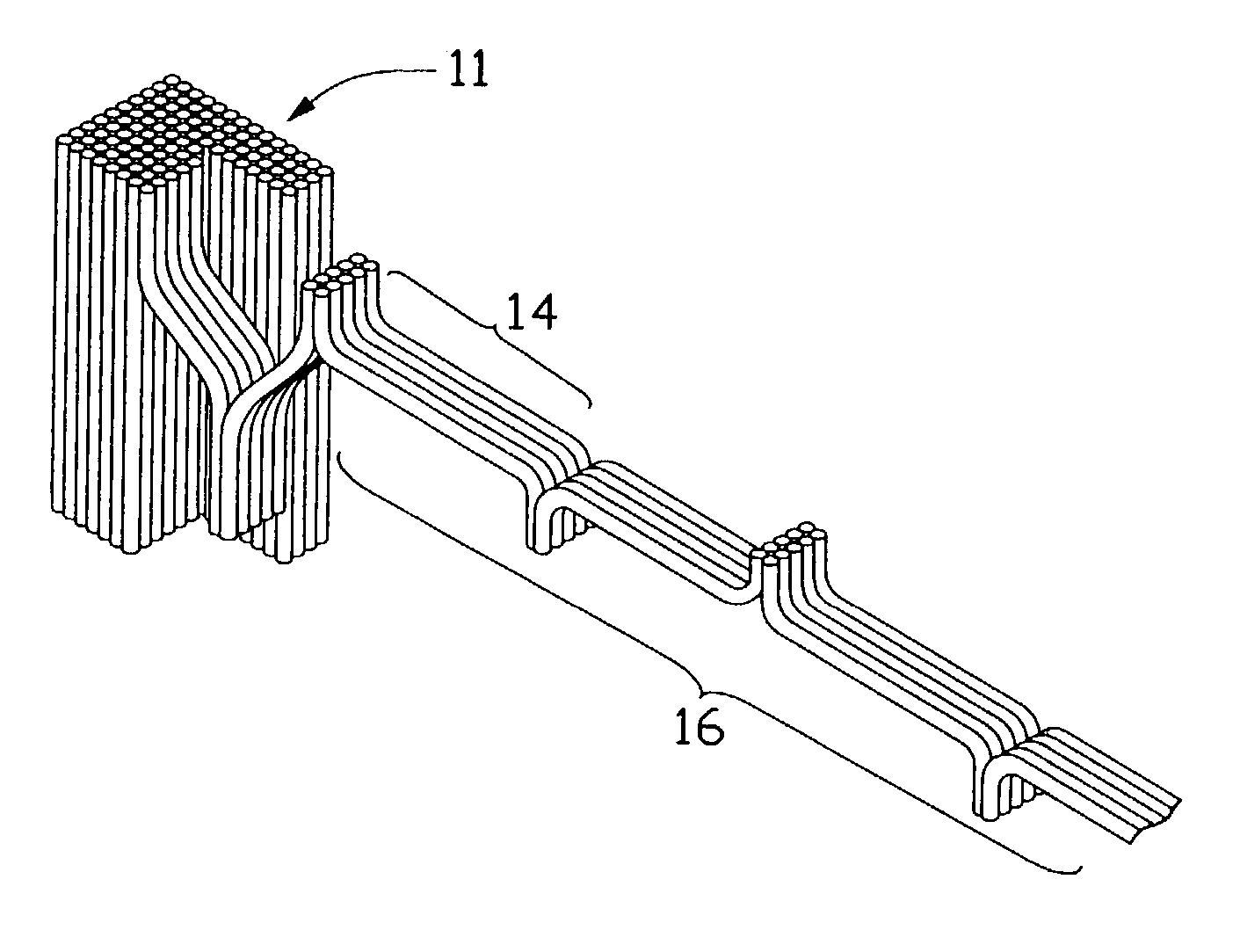
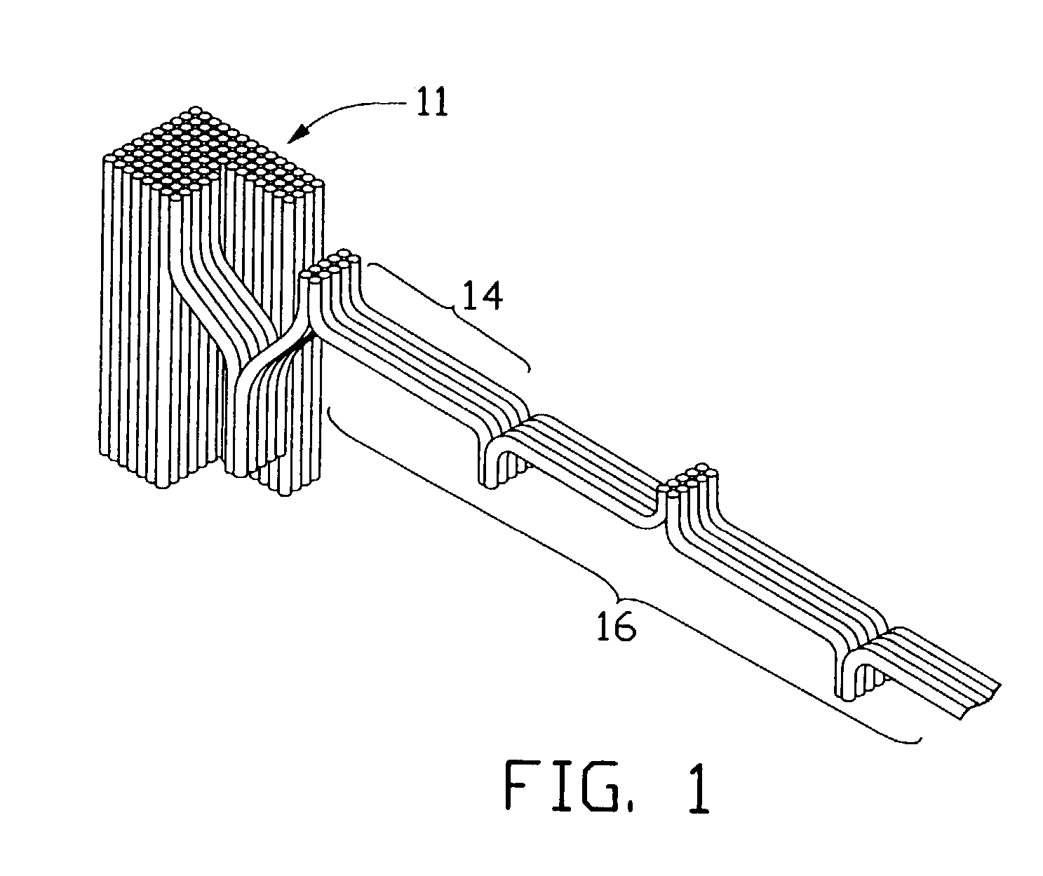
[0021]Step 1. Forming an array 11 of carbon nanotubes, discussed in greater detail below.

[0022]Firstly, a substrate is provided. The substrate includes a silicon wafer, which is two inches in diameter and 350 μm thick. An 800 nm thick thermal-oxidized layer is formed on the silicon wafer. A surface of the thermal-oxidized layer is flat and smooth, to enable growth of a large-scale array of carbon nanotubes. Then an iron thin film that is 5 nm thick is deposited on the substrate by electron beam evaporation, and is subsequently annealed in air at 300˜400° C. for 10 hours to form a ferrous oxide film. Then the ferrous oxide film is reduced to pure iron by reaction with hydrogen or ammonia, so that the pure iron can be used as a catalyst.

[0023]The substrate is then preferably diced into a plurality of rectangular pieces. Each such piece is put into a quartz boat, which is subsequently inserted into the center of a one-inch qu...


PUM

PropertyMeasurementUnit
temperatureaaaaaaaaaa
thicknessaaaaaaaaaa
temperatureaaaaaaaaaa

Abstract

A method of fabricating a long carbon nanotube yarn includes the following steps: (1) providing a flat and smooth substrate; (2) depositing a catalyst on the substrate; (3) positioning the substrate with the catalyst in a furnace; (4) heating the furnace to a predetermined temperature; (5) supplying a mixture of carbon containing gas and protecting gas into the furnace; (6) controlling a difference between the local temperature of the catalyst and the furnace temperature to be at least 50° C.; (7) controlling the partial pressure of the carbon containing gas to be less than 0.2; (8) growing a number of carbon nanotubes on the substrate such that a carbon nanotube array is formed on the substrate; and (9) drawing out a bundle of carbon nanotubes from the carbon nanotube array such that a carbon nanotube yarn is formed.

Description

BACKGROUND OF THE INVENTION[0001]1. Field of the Invention[0002]The present invention relates to a method for fabricating a nanotube structure, and more particularly to a method for fabricating a carbon nanotube yarn.[0003]2. Description of Prior Art[0004]Since being discovered in 1991, carbon nanotubes have been synthesized by numerous methods such as laser vaporization, arc discharge, pyrolysis and plasma-enhanced or thermal chemical vapor deposition. However, all carbon nanotubes which have been produced by these methods are short in length, the longest carbon nanotubes being only several-hundred micrometers in length. These short lengths restrict the applications of carbon nanotubes. In particular, such short lengths are not suitable for use in macroscopic objects, such as bullet proof vests and fabrics that block electromagnetic waves.[0005]Therefore, a method for fabricating long carbon nanotube structures or yarns is desired.SUMMARY OF THE INVENTION[0006]Accordingly, an objec...

Claims


Application Information

Patent Timeline
Patent Type & Authority Patents(United States)
IPC IPC(8): D01F9/12C01B31/02B01J23/74B01J35/06B01J37/02B01J37/34D01F9/127
CPCB01J23/74B82Y30/00D01F9/1275B01J35/06B01J37/0238B01J37/341Y10T428/2913Y10T428/294Y10T428/2938Y10T428/2958Y10T428/2933Y10T428/2918B01J35/58
Inventor JIANG, KAILIFAN, SHOUSHANLI, QUNQING
Owner HON HAI PRECISION IND CO LTD
Learn More