
System and method for state restoration in a diagnostic module for a high-speed microprocessor

Inactive Publication Date: 2006-05-09
AVAGO TECH WIRELESS IP SINGAPORE PTE
View PDF4 Cites 66 Cited by
  • Summary
  • Abstract
  • Description
  • Claims
  • Application Information

AI Technical Summary

Benefits of technology

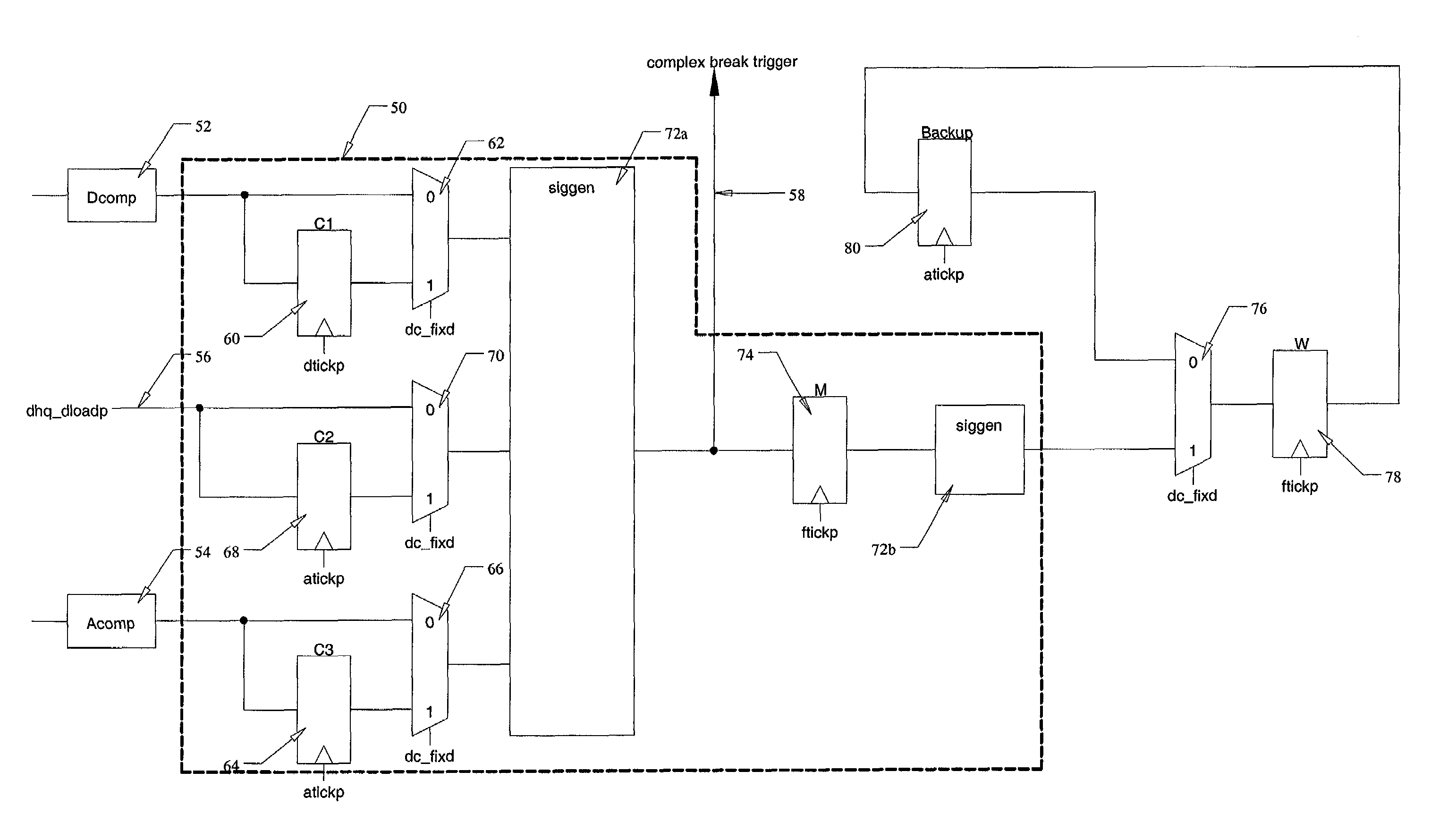
[0013]A microprocessor with an associated diagnostic module is also disclosed herein. The diagnostic module changes its internal state in response to trigger events created by the microprocessor, and is capable of halting the microprocessor in response to combinations of these trigger events and its own previous internal states. Trigger events occur when the microprocessor accesses specified memory locations or specified data values. Invalid trigger events may result when the microprocessor's exception handler causes the re-execution of a branch instruction, following the return from an exception occurring during the fix-up cycle inserted to handle a data load miss associated with an instruction in the branch delay slot (i.e. the location immediately following the branch instruction). Advantageously, the diagnostic module disclosed herein avoids erroneously updating its internal state twice for the same branch instruction. A backup register saves the internal state of the diagnostic module prior to each state change, and restores the previous state when a state change is induced by an invalid trigger event.

Problems solved by technology

This results in the branch instruction being re-executed, creating a spurious trigger event, which causes the state machine to be updated twice for the same instruction.
An invalid trigger event may result when the microprocessor's exception handler causes the re-execution of a branch instruction, upon returning from an exception occurring within the fix-up cycle inserted to handle a data load miss associated with the instruction immediately following the branch (i.e., in the branch delay slot).

Method used


Image

  • System and method for state restoration in a diagnostic module for a high-speed microprocessor
  • System and method for state restoration in a diagnostic module for a high-speed microprocessor
  • System and method for state restoration in a diagnostic module for a high-speed microprocessor

Examples


Embodiment Construction

[0021]Modern high-performance microprocessors are sophisticated, highly-integrated devices, employing numerous internal and external signals, and operating at very high clock rates. A number of performance-enhancing architectural features are present in these microprocessors. Unfortunately, some of these features also complicate testing of the processor.

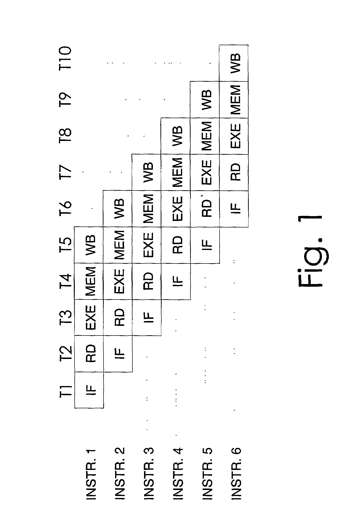
[0022]In a standard microprocessor, memory latency limits the speed at which instructions may be completed, since memory instructions cannot complete until data is back from memory, enabling the processing of the next instruction in the sequence. No matter how fast the processor, overall throughput cannot exceed the speed with which the memory can be accessed. If necessary, a fast processor may insert “wait states” into its memory accesses to compensate for slower memory devices. Since no useful work is done by the processor during these wait states, they represent wasted processor cycles.

[0023]The microprocessor may interface to var...


PUM


Abstract

A system and method are presented for saving and restoring the state of a diagnostic module in a microprocessor. The diagnostic module contains a complex break state machine, capable of halting the microprocessor at specified breakpoints. These breakpoints are based on combinations of instruction locations and / or data values, along with previous machine states. A problem occurs with prior art diagnostic modules when the processor returns from an exception occurring during a fix-up cycle inserted to handle a data load miss associated with an instruction located in a branch delay slot (the location immediately following a conditional branch instruction). Under these circumstances, the exception handler restores the program counter to the location of the branch instruction, causing the branch to be re-executed. The prior art state machine erroneously updates its internal state a second time when the branch is re-executed. According to the system and method disclosed herein, at each state change the previous machine state saved. Thus, when a branch instruction is re-executed, the complex break state machine of the present invention is restored to its previous state, thereby correcting the error.

Description

BACKGROUND OF THE INVENTION[0001]1. Field of Invention[0002]This invention relates to microprocessor design, and more particularly, to the implementation of on-chip debug capability in a microprocessor.[0003]2. Description of Related Art[0004]Modern microprocessors offer unprecedented performance. For a variety of digital integrated circuits (IC's), speed, level of integration (i.e. transistors per square centimeter) and capabilities have improved. Moreover, in many cases, these performance improvements have been accompanied by reductions in size, power consumption and cost of the devices. However, these benefits require greater complexity in digital logic design. Because of this complexity, the investment of time and resources by the manufacturer to design and fabricate a digital logic device has increased. For this same reason, the possibility of a mistake or oversight on the part of the designer has become more likely.[0005]An architectural feature common to most high performance...

Claims


Application Information

Patent Timeline
Patent Type & Authority Patents(United States)
IPC IPC(8): G06F17/50G06F9/00
CPCG06F9/3842G06F9/3863G06F11/3664Y10S707/99957Y10S707/99953
Inventor LIN, SHUAIBIN
Owner AVAGO TECH WIRELESS IP SINGAPORE PTE
Learn More