Magnetron plasma source

a plasma source and magneto-plasma technology, applied in the direction of electric lighting sources, electric discharge lamps, coatings, etc., can solve the problems of reducing the life of the cathode, reducing the efficiency of the cathode, and increasing the overall pumping load, so as to achieve the effect of large and more expensive vacuum pumps

Inactive Publication Date: 2006-05-02
GENERAL PLASMA
View PDF23 Cites 12 Cited by
  • Summary
  • Abstract
  • Description
  • Claims
  • Application Information

AI Technical Summary

Problems solved by technology

The difficulty with this source, as with all sources implementing thermionic emitting cathodes, is the cathode life is shortened by contact with oxygen gas.
The inability to directly ‘burn’ oxygen creates several limitations and challenges: 1) The argon purge gas adds to the overall pumping load mandating larger and more expensive vacuum pumps.
2) The downstream activation / ionization of the oxygen gas is less efficient than ionizing the process gas inside the plasma source.
And 4) Even with the argon purge gas, the expensive cathode requires replacement at accelerated intervals when oxygen is used in the process.

Method used


Image

  • Magnetron plasma source
  • Magnetron plasma source
  • Magnetron plasma source

Examples


Embodiment Construction

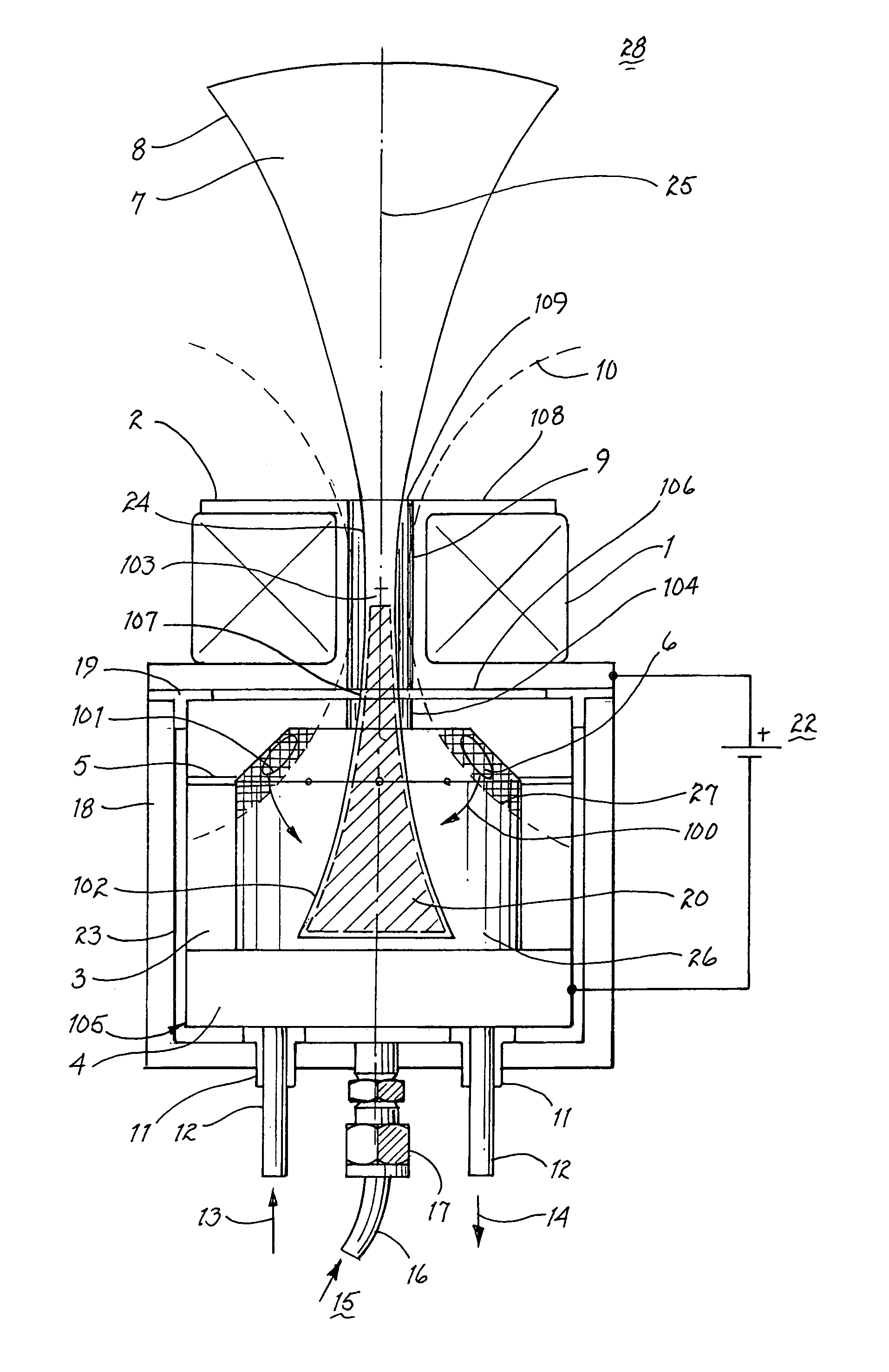
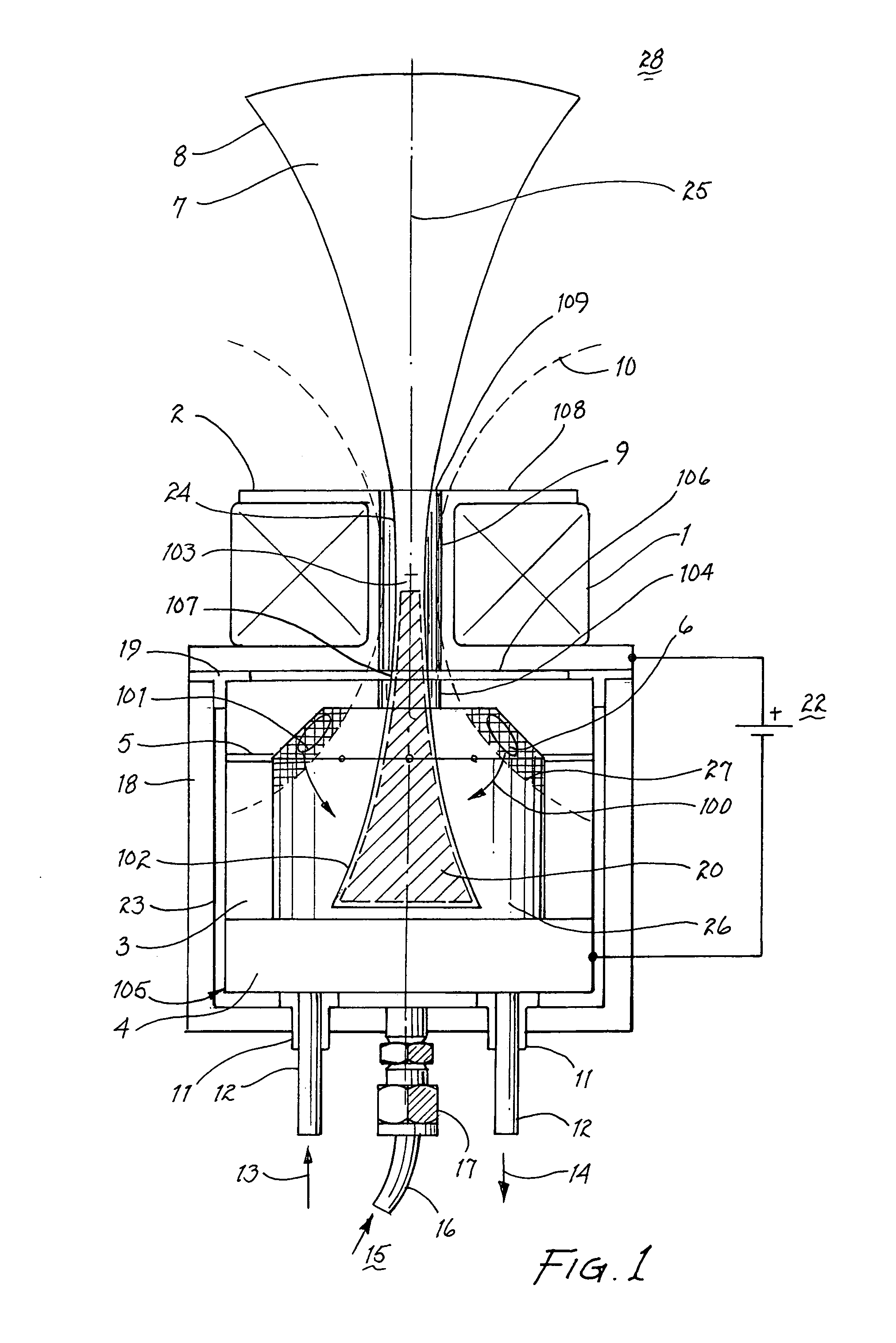
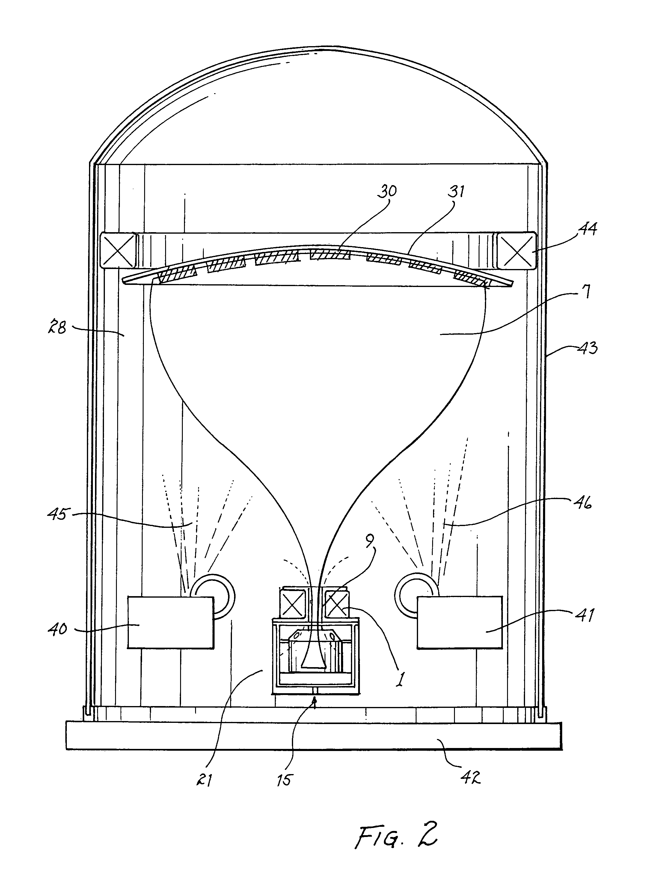
[0022]FIG. 1 shows a section view of a magnetron plasma source 21. The source exists in a vacuum such as process chamber 28 (FIG. 2). The preferred embodiment shown is a round source, as indicated by centerline 25. Electromagnet coil 1 is wound on and supported by spool 2. Spool 2 is axis symmetric with discharge cavity 26 and comprises a first end 106 formed to include a first aperture 107, a second end 108 formed to include a second aperture 109, and a conduit nozzle 9 extending through the spool interconnecting the first aperture and the second aperture, where the first end of spool 2 is adjacent to the top portion of discharge cavity 26, such that nozzle 9 interconnects discharge cavity 26, and process chamber 28 (FIG. 2).

[0023]The electromagnet 1 is water cooled by flowing water through a current carrying hollow conductor (not shown). Fabrication of water cooled electromagnets is well known and other techniques may be used. For low power applications or by design, the electroma...


PUM

PropertyMeasurementUnit
Magnetic fieldaaaaaaaaaa
Efficiencyaaaaaaaaaa

Abstract

A point projection type flood plasma source implements a magnetron sputter cold cathode electron source in a discharge cavity separated from a process chamber by a narrow conduit and a solenoid magnetic field. The solenoid magnetic field impedes radial electron flow in the nozzle and the process chamber. Process gas flows into the discharge cavity and through the nozzle to the process chamber. This gas is ionized in the nozzle and the process chamber by electrons trapped in the solenoid magnetic field. The result is a dense plasma plume in the process chamber useful for a number of applications. The source has particular advantages for reactive gas processes such as those requiring oxygen.

Description

[0001]This application claims benefit of Ser. No. 60 / 467,696, filed on May 2, 2003.[0002]The invention relates to a magnetron plasma source.FIELD OF THE INVENTION[0003]The invention relates to a magnetron plasma source.BACKGROUND OF THE INVENTION[0004]The present invention relates to electron, plasma and ion sources for industrial and space propulsion applications. Plasma and ion sources have found important industrial uses particularly in the semiconductor, telecom and optics fields. Another application for plasma and ion sources is as electric engines for space vehicle propulsion. To address these applications a wide variety of sources have been developed. One group of sources can be described as point projection sources. These plasma or ion sources typically include a discharge cavity where plasma is generated and a means to expel or accelerate the plasma or ions from this cavity into a process chamber. Several of these sources implement magnetic fields to control electron motion...

Claims


Application Information

Patent Timeline
IPC IPC(8): H01J7/24H01J37/34
CPCH01J37/3405
Inventor MADOCKS, JOHN
Owner GENERAL PLASMA
Why Eureka
Try Eureka