Eureka AIR delivers breakthrough ideas for toughest innovation challenges, trusted by R&D personnel around the world.

Apparatus of Plural Charged-Particle Beams

a technology of charged particles and apparatuses, applied in electrical apparatuses, electric discharge tubes, basic electric elements, etc., can solve the problems of reducing the yield to a great degree, reducing the capacity of conventional yield management tools with optical beams, and not providing throughputs competent for mass production, etc., to achieve high throughput and resolution. high

Active Publication Date: 2016-09-15
ASML NETHERLANDS BV
View PDF3 Cites 78 Cited by
  • Summary
  • Abstract
  • Description
  • Claims
  • Application Information

AI Technical Summary

Benefits of technology

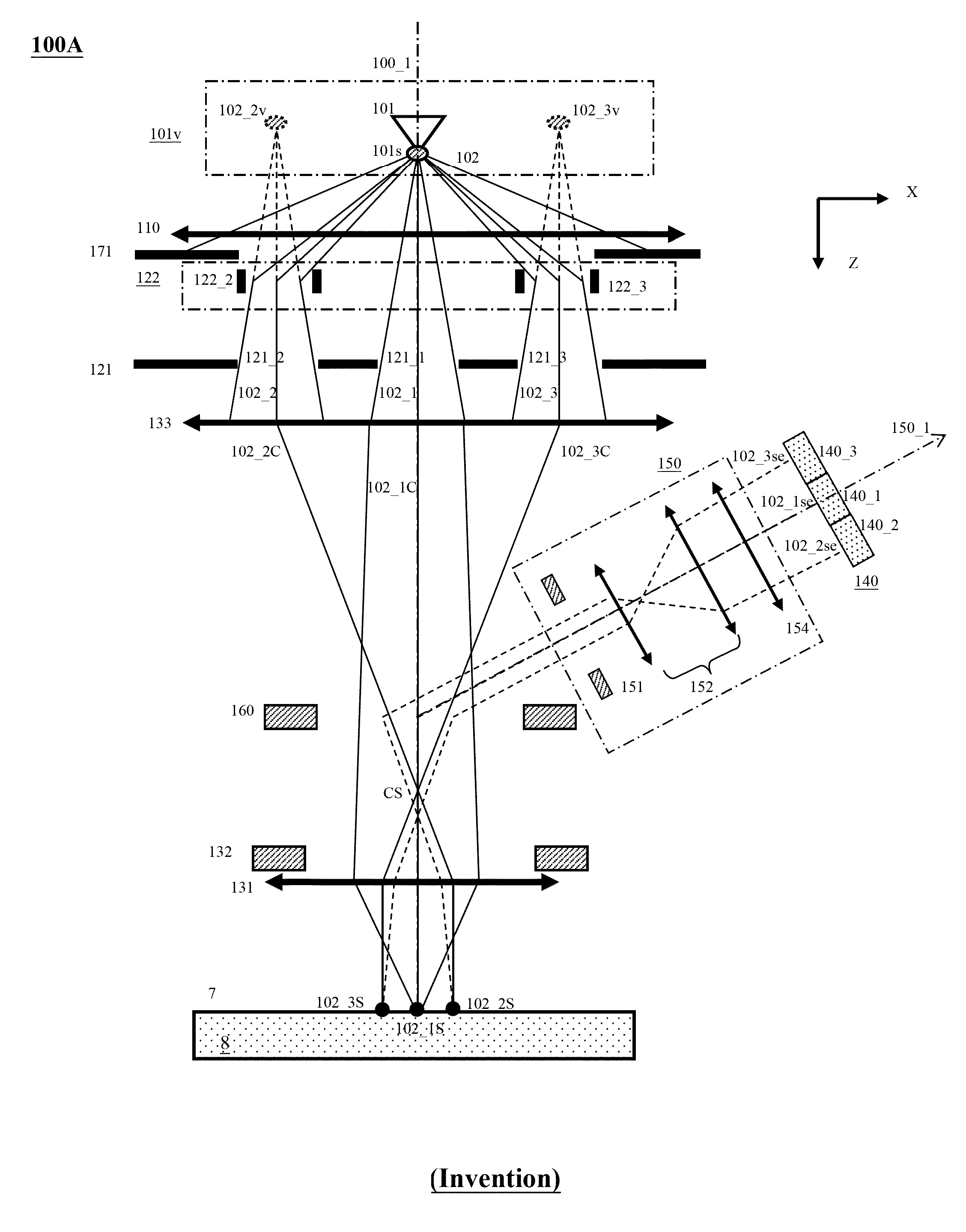
This patent describes a new apparatus for observing samples and inspecting defects in semiconductor manufacturing. It uses multiple beams that form virtual images of an electron source, which are then limited and adjusted to form probe spots on the sample surface. The apparatus also detects secondary electron beams that are deflected away from the primary beam path. The technical effects of this invention include high resolution and high throughput for observing samples, as well as improved yield management for inspecting and reviewing defects on wafers and masks.

Problems solved by technology

For manufacturing semiconductor IC chips, pattern defects and / or uninvited particles (residuals) inevitably appear on surfaces of wafers / masks during fabrication processes, which reduce the yield to a great degree.
Accordingly, the conventional yield management tools with optical beam gradually become incompetent due to diffraction effect, and yield management tools with electron beam are more and more employed.
Currently, the yield management tools with electron beam employ the principle of scanning electron microscope (SEM) with a single electron beam, which therefore can provide higher resolution but can not provide throughputs competent for mass production.
Although the higher and higher beam currents can be used to increase the throughputs, the superior spatial resolutions will be fundamentally deteriorated by Coulomb Effect.
The scattering electrons in each beamlet will enlarge the probe spot and / or become a background noise and therefore deteriorate the image resolution of the corresponding scanned region.
It is very time-consuming to change the group in use.
In addition, the secondary electron beams can only be focused onto the multiple detection elements of the in-lens detector in some specific operation conditions of the objective lens.
Therefore the available applications are limit.

Method used


Image

  • Apparatus of Plural Charged-Particle Beams
  • Apparatus of Plural Charged-Particle Beams
  • Apparatus of Plural Charged-Particle Beams

Examples


Embodiment Construction

[0042]Various example embodiments of the present invention will now be described more fully with reference to the accompanying drawings in which some example embodiments of the invention are shown. Without limiting the scope of the protection of the present invention, all the description and drawings of the embodiments will exemplarily be referred to an electron beam. However, the embodiments are not be used to limit the present invention to specific charged particles.

[0043]In the drawings, relative dimensions of each component and among every component may be exaggerated for clarity. Within the following description of the drawings the same or like reference numbers refer to the same or like components or entities, and only the differences with respect to the individual embodiments are described. For sake of clarity, only three beamlets are available in the drawings, but the number of beamlets can be anyone.

[0044]Accordingly, while example embodiments of the invention are capable o...


PUM


Abstract

A multi-beam apparatus for observing a sample with high resolution and high throughput is proposed. In the apparatus, a source-conversion unit changes a single electron source into a virtual multi-source array, a primary projection imaging system projects the array to form plural probe spots on the sample, and a condenser lens adjusts the currents of the plural probe spots. In the source-conversion unit, the image-forming means is on the upstream of the beamlet-limit means, and thereby generating less scattered electrons. The image-forming means not only forms the virtual multi-source array, but also compensates the off-axis aberrations of the plurality of probe spots.

Description

CLAIM OF PRIORITY[0001]This application claims the benefit of priority of U.S. provisional application No. 62 / 130,819 entitled to Ren et al. filed Mar. 10, 2015 and entitled “Apparatus of Plural Charged-Particle Beams”, the entire disclosures of which are incorporated herein by reference.BACKGROUND OF THE INVENTION[0002]1. Field of the Invention[0003]The present invention relates to a charged-particle apparatus with a plurality of charged-particle beams. More particularly, it relates to an apparatus which employs plural charged-particle beams to simultaneously acquire images of plural scanned regions of an observed area on a sample surface. Hence, the apparatus can be used to inspect and / or review defects on wafers / masks with high resolution and high throughput in semiconductor manufacturing industry.[0004]2. Description of the Prior Art[0005]For manufacturing semiconductor IC chips, pattern defects and / or uninvited particles (residuals) inevitably appear on surfaces of wafers / masks...

Claims


Application Information

Patent Timeline
Patent Type & Authority Applications(United States)
IPC IPC(8): H01J37/147H01J37/10H01J37/28H01J37/06
CPCH01J37/1474H01J37/06H01J2237/083H01J37/28H01J37/10H01J2237/04924H01J2237/1205H01J2237/1516H01J37/1472H01J2237/2817H01J37/1477H01J37/12
Inventor REN, WEIMINGLI, SHUAILIU, XUEDONGCHEN, ZHONGWEI
Owner ASML NETHERLANDS BV
Why Eureka
Eureka Blog
Learn More