Remote sensing apparatus and method

a remote sensing and sensor technology, applied in the direction of optical radiation measurement, instruments, spectrometry/spectrophotometry/monochromators, etc., can solve the problems of affecting the accuracy of the measurement is reduced, so as to achieve accurate measurement of the intensity of spectral energy and easy determination

Inactive Publication Date: 2006-05-02
THE BOEING CO
View PDF5 Cites 48 Cited by
  • Summary
  • Abstract
  • Description
  • Claims
  • Application Information

AI Technical Summary

Benefits of technology

[0019]The remote sensing apparatus and method of the present invention provide efficient techniques for accurately measuring the intensity of spectral energy from a remote object, such as in multispectral and hyperspectral applications. The accuracy of the measurements is due to the design of the remote sensing apparatus, which has multiple optical fibers that direct the spectral energy to detectors. Specifically, the focal plane of an optical system is occupied by one end of a group of optical fibers, and a plurality of detectors are coupled to the other end of the optical fibers, such that each detector is advantageously coupled to a single optical fiber. Because the in-track focal plane extent of the remote sensing apparatus is much smaller than that of conventional sensors, and because each detector is coupled to a single optical fiber, such that the amount of energy received by each detector is known or may be easily determined, the apparatus and method provide the necessary information for creating an accurate image of the remote object, without the need for complicated corrections.
[0028]Thus, the remote sensing apparatus and method for detecting spectral energy provide efficient and effective techniques for measuring the intensity of spectral energy that is received from a remote location. The measurements require less complicated correction calculations than the spectral energy intensity measurements made by conventional remote sensors because the focal plane of the present remote sensing apparatus is more compact, and the amount of spectral energy incident upon each detector is known or may be easily determined. In addition, the compact focal plane and the flexibility in position and orientation of the energy-receiving elements provided by the remote sensing apparatus and method increases the flexibility in designing optical sensors with large numbers of detectors that enable multiple spectral bands and large fields of view to be detected.

Problems solved by technology

The processing element is required to correct for the difference in scene position observed by different rows of detectors, and this correction becomes more difficult and less accurate as the in-track extent of the detector array increases.
For example, for the sensor described above, a 100 meter error in determining the elevation of the scene results in up to a 2-meter error in determining the relative position of pixels from different rows of detectors.
During this time, the satellite or aircraft carrying the sensor can change orientation, i.e., pitch, yaw, or roll, resulting in errors in determining the relative position of pixels from different rows of detectors.
Furthermore, the in-track extent of the detector array also requires that the optical system provide a high-quality image over this in-track extent, which may be difficult to do while maintaining acceptable optical system performance in other respects, such as aberrations and optical distortions.
It is difficult, however, to maintain the alignment of mirrors to the detectors because temperature changes may cause the mirrors to slightly change position.
In addition, the mirrors require a relatively significant amount of space in front of the focal plane, such that mirrors typically may only be used to separate 2 or 3 spectral bands.
These embodiments, however, are difficult to utilize, particularly when the desired spectral bands are close together or overlap, because the rows of detectors also overlap.
Additionally, because wavelength and physical position in the focal plane are directly related in these embodiments, certain design options are precluded.
For example, it is not possible to provide two or more rows of detectors that are sensitive to the same spectral band, which is commonly done to improve sensitivity or provide redundancy in case of detector failure.
In addition, it is difficult to utilize a dispersive element when the detector array is too wide in the cross-track direction to use a single detector chip, because it is difficult or impossible to align multiple dispersive elements and multiple chips with sufficient accuracy to maintain a uniform spectral response.
The drawback to this configuration, however, is that random subgroups of the optical fibers illuminate each detector, which makes it impossible to control how much light is transmitted to each detector.
Therefore, the effective sensitivity of each detector is different, and uniform images are difficult to create.
In addition, the spatial response of each detector (i.e., the response to a point source of radiation in the scene as a function of the point source position) is complex, and differs from detector to detector.
Therefore, because there is no way to know whether the electrical signals that are read by the processing element are consistent, an incorrect or misleading image of the scene or target may be created.
Although it is possible to know how much light is transmitted to the detector in the configuration in which one fiber transmits energy to one detector, the drawback is that each assembly of detector and fiber is physically separate, and only a small number of detector / fiber pairs (i.e., 100 or less) may be practically utilized in a sensor, which prevents this configuration from being used in pushbroom imaging applications.

Method used


Image

  • Remote sensing apparatus and method
  • Remote sensing apparatus and method
  • Remote sensing apparatus and method

Examples


Embodiment Construction

[0039]The present inventions now will be described more fully hereinafter with reference to the accompanying drawings, in which some, but not all embodiments of the invention are shown. Indeed, these inventions may be embodied in many different forms and should not be construed as limited to the embodiments set forth herein; rather, these embodiments are provided so that this disclosure will satisfy applicable legal requirements. Like numbers refer to like elements throughout.

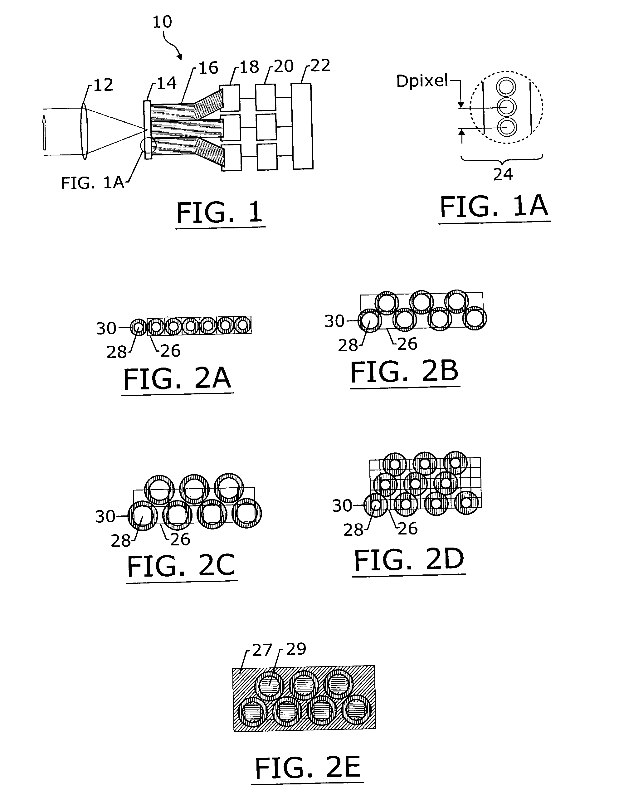
[0040]The remote sensing apparatus and method for detecting spectral energy provide efficient and effective techniques for measuring the intensity of spectral energy that is received from a remote location. The measurements are more accurate and require less complicated correction calculations than the spectral energy intensity measurements made by conventional remote sensors because the in-track focal plane extent of the present remote sensing apparatus is more compact, while continuing to provide a sufficient...


PUM


Abstract

The remote sensing apparatus and method include optical fibers and detectors. One end of the optical fibers is located in a focal plane of an optical system, with the end of each optical fiber collecting spectral energy arriving at a particular location in the focal plane. Each detector is coupled to the other end of a single optical fiber, and the detector measures the intensity of the spectral energy emitted by the optical fiber. Sets of detectors may also be utilized, such that each set of detectors is optically coupled to a respective fiber, and at least one separation element separates the spectral energy emitted by each optical fiber into a plurality of spectral bands. Each detector in each set of detectors then receives a respective spectral band emitted by a respective optical fiber.

Description

BACKGROUND OF THE INVENTION[0001]The present invention relates to a remote sensing apparatus and method having a focal plane occupied by one end of a group of optical fibers, and a plurality of detectors coupled to the other end of the optical fibers such that each detector is advantageously coupled to a single optical fiber in order to accurately measure the intensity of light from a single location in the focal plane.[0002]Remote sensing devices detect and measure energy reflected and / or emanating from remote objects in order to determine physical properties of the objects and, in some instances, to identify the materials from which the remote objects are formed. For example, remote sensing devices operating in the visible and infrared regions of the electromagnetic spectrum are used extensively to measure the characteristics of the Earth's land surface, ocean surface, and atmosphere as a function of position, as well as the characteristics of other bodies in the Solar System. The...

Claims


Application Information

Patent Timeline
IPC IPC(8): G01J1/42G02B6/00G01J1/04G01J3/02G01J3/28G02B6/06G02B6/36G02B6/42
CPCG01J1/0425G01J1/4228G01J3/02G01J3/0218G01J3/0229G01J3/0256G01J3/2803G01J3/2823G02B6/06G01J1/04G01J1/0204G02B6/4214G01J1/0488G02B6/3668G02B6/3672G02B6/368
Inventor KARE, JORDIN T.TURNER, ROBERT W.
Owner THE BOEING CO
Why Eureka
Try Eureka