
Setting tool

Inactive Publication Date: 2006-04-18
HILTI AG
View PDF5 Cites 3 Cited by
  • Summary
  • Abstract
  • Description
  • Claims
  • Application Information

AI Technical Summary

Benefits of technology

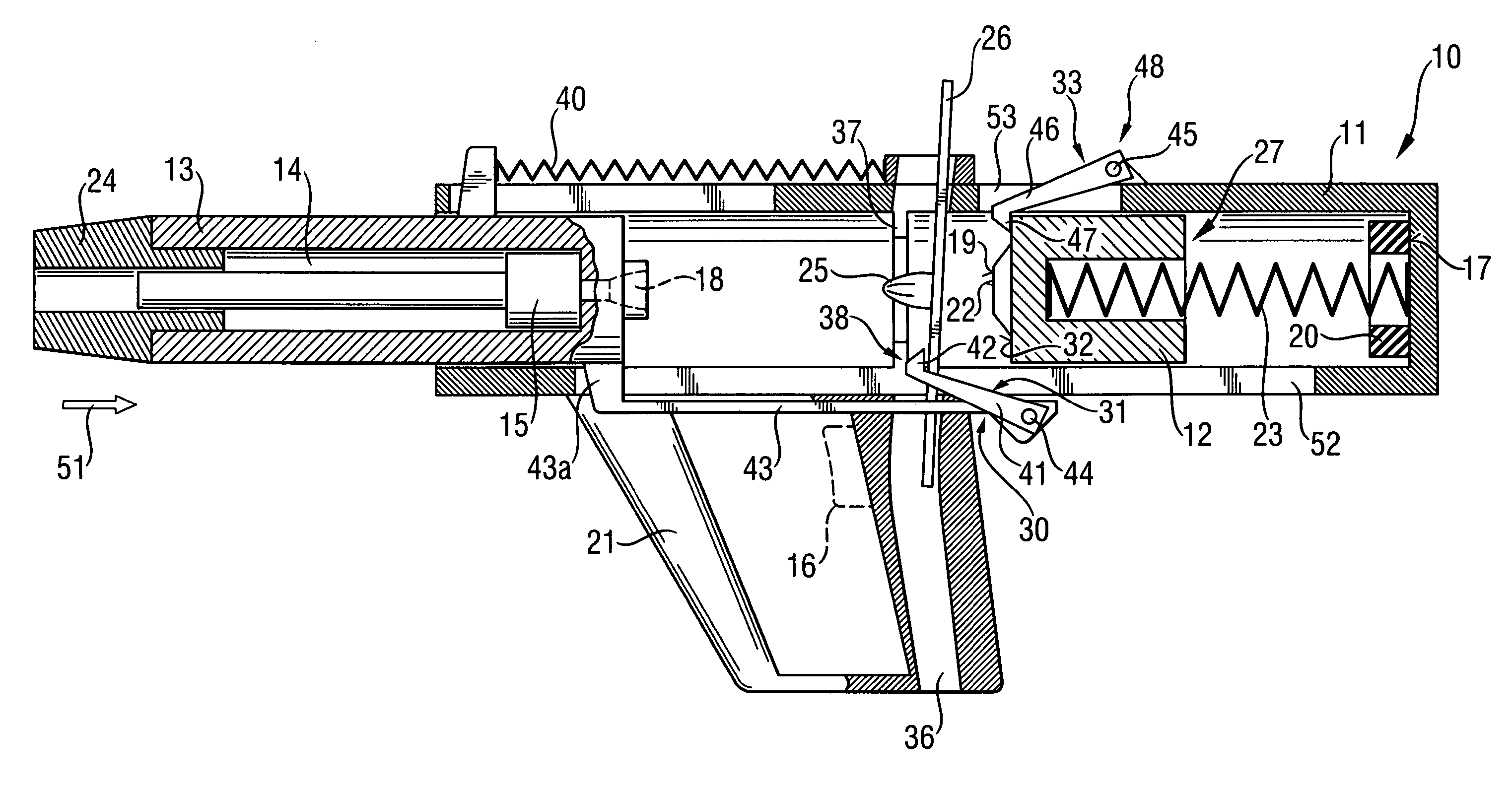
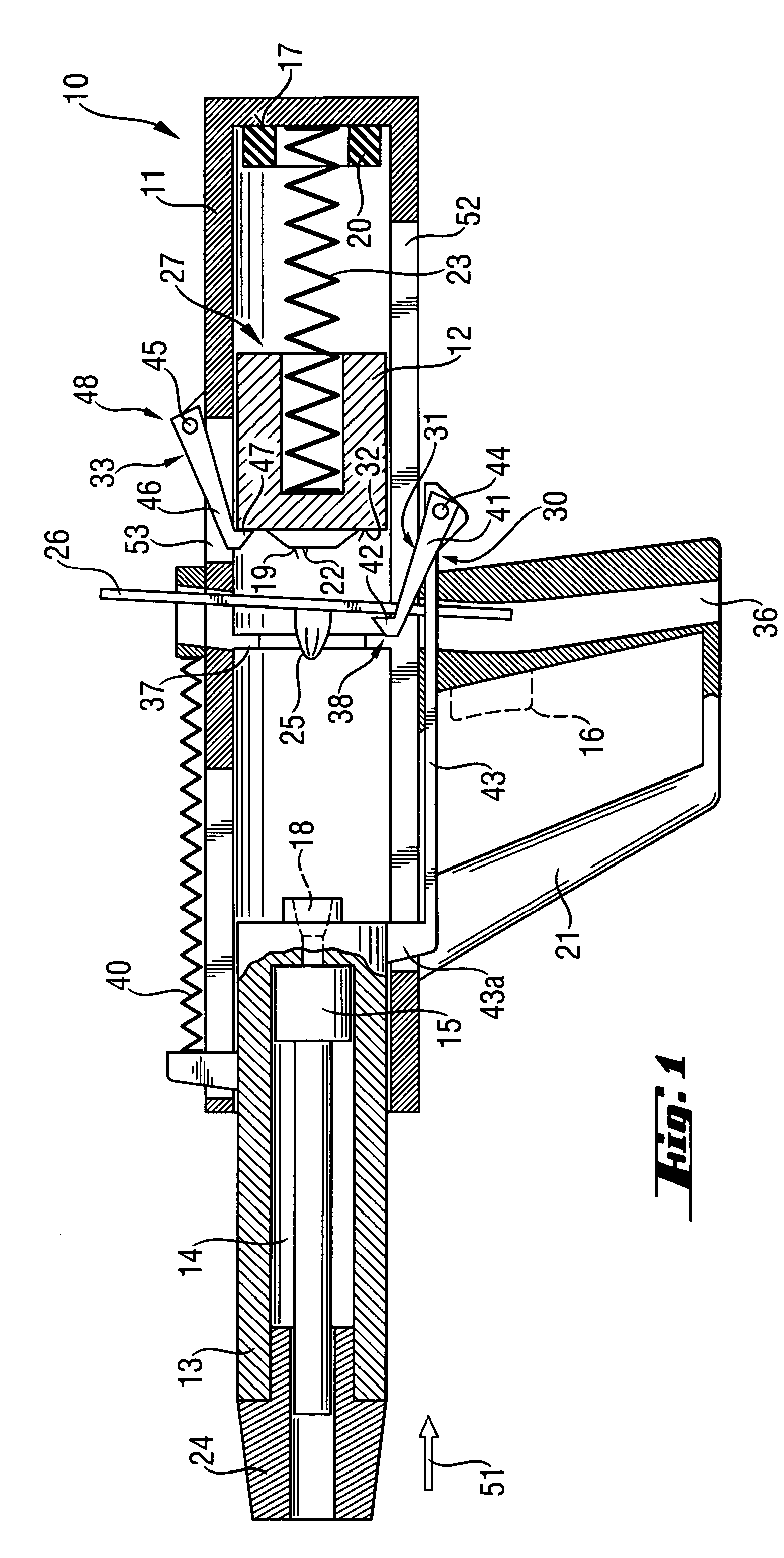
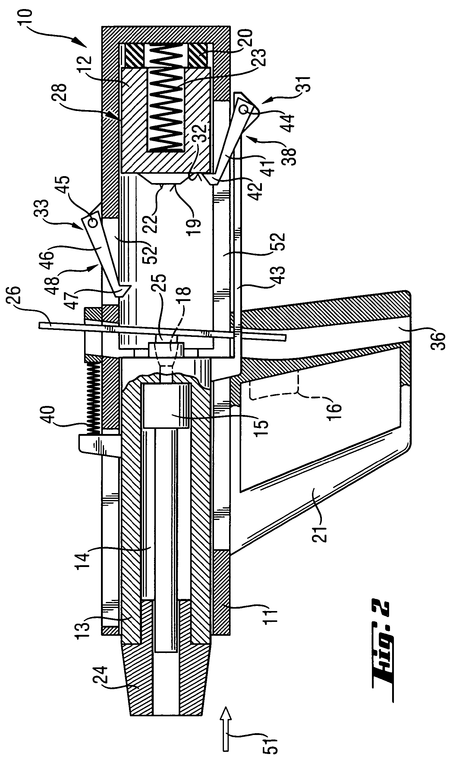
[0007]A setting tool according to the present invention is characterized by a locking device or mechanism with which the ignition unit is held in a pre-loaded position against an energy accumulator in which the cartridge chamber remains open. Upon actuation of appropriate actuation means, the locking device releases the ignition unit which is displaced in its ignition position by the energy accumulator. The cartridge chamber bottom, which is carried by the ignition unit, closes the cartridge chamber, and the ignition element, which is also carried by the ignition unit, ignites the propellant enclosed in the cartridge chamber. The elements according to the present invention insure that the propellant remains in the cartridge chamber for a very short time and that the cartridge chamber, which becomes heated after a prolong use of the setting tool is held at a distance from the cartridge strip. The ignition unit is displaced into its ignition position after actuation of the ignition process very rapidly, so that the thermal conditions, which lead to an undesirable ignition of the propellant, are prevented.
[0008]In an ideal case, the ignition element, e.g., an ignition peg or pin is fixedly secured on the ignition unit and is displaceable therewith. This permits to initiate ignition of the propellant simultaneously with the closing of the cartridge chamber with the cartridge chamber bottom that is carried by the ignition unit. The present invention permits to eliminate a number of components and manufacturing processes during manufacturing of the setting tool, as there is no need in a separate, displaceable ignition pin.
[0009]The locking device according to the present invention can include at least one locking element, which can be formed, e.g., as a pivotally supported locking pawl. In the locking position of the locking device or the locking element, the pawl section of the locking pawl extends into the displacement path of the ignition unit, holding the ignition unit against a biasing force of the energy accumulator acting on the ignition unit. The locking pawl can be pivoted out of the displacement path of the ignition unit with a very simple mechanism, e.g., upon actuation of the actuation switch. Preferably, in an advantageous embodiment of the present invention, the locking element or the locking pawl is supported on a bearing axle supported on the housing, which permits to obtain a very robust constructions.
[0012]In an advantageous embodiment of the present invention, the setting tool is provided with a safety element, e.g., a catch pawl. The safety element extends, in its safety or locking position, into the displacement path of the ignition unit. With the safety element, the catch pawl, the ignition unit can be held back, upon opening of the cartridge chamber as a result of spring-back or recoil of the ignition unit, from impacting the cartridge chamber again. This advantageously prevents multi-ignition of the propellants located in the cartridge chamber during a setting process.
[0018]According to another advantageous embodiment of the present invention, the guide for the cartridge strip is secured at the front end of the ignition unit on its side facing the cartridge chamber and is displaceable with the ignition unit. With this arrangement of the cartridge strip guide, heat transmission from a heated cartridge chamber to the cartridge strip, in the inoperative position of the setting tool, is also prevented.

Problems solved by technology

The drawback of the known setting tool consists in that because of a comparatively long time the propellant is enclosed in the cartridge chamber, after a prolong operation of the setting tool, the propellant can self-ignite because of heating of the cartridge chamber.

Method used


Image

  • Setting tool
  • Setting tool
  • Setting tool

Examples


first embodiment

[0031]A setting tool 10 according to the invention and which is shown in its inoperative position in FIG. 1, includes a one- or multi-part housing 11 and a piston guide 13 supported in the housing 11. A piston 15 is displaceably supported in a hollow chamber 14 of the piston guide 13. The piston 15 is driven by propellant 25 or its expending combustion gases. In the embodiment shown in FIGS. 1–5, a handle 21 is secured on the housing 11. The handle 21 carries an actuation switch 16 for initiating a setting process by a user of the setting tool 10. The handle 21, which is shown in FIGS. 1–5, is not shown in FIGS. 6–10, though the setting tool shown in FIGS. 6–10 can also be provided with a similar handle. It should be understood that the setting tool 10, in addition to the housing 11, can have further housing components or an outer protection housing formed, e.g, of a plastic material.

[0032]The piston guide 13 is displaceable arranged in a sleeve-shaped housing 11 and is supported ag...

second embodiment

[0046]FIG. 6 shows the setting tool 10 in its inoperative position in which the setting tool 10 is ready to be ignited, with the ignition unit 12 located in its pre-loaded position 28 against the energy accumulator 23. The ignition unit 12 is held in this position by the locking pawl 41. The piston guide 13 projects out of the housing 11, and the catch pawl 46 projects into the interior of the housing 11 for catching the ignition unit 12 in case it is displaced, for some reason, forward, without the actuation of the setting tool 10.

[0047]FIG. 7 shows a position in which the setting tool 10 is pressed against a constructional component. The piston guide 13 is displaced into the housing 11. The catch pawl 46 is pivoted out of the interior of the housing 11 by the crank means 54. However, the locking pawl 41 still engages the ignition unit 12, retaining it in its pre-loaded position 28.

[0048]FIG. 8 shows a position in which the actuation switch (discussed with reference to FIG. 1) has...

third embodiment

[0053]FIG. 9 shows the setting tool 10 according to the present invention in its inoperative position. The ignition unit 12 is held by the catch pawl 46, which is located in its locking position 48, in its intermediate position 27. When the setting tool 10 is pressed against a constructional component, the servo-component 43 and the locking pawl 41, which is carried thereby, are displaced together with the bolt guide in the direction 51. The guide unit 12 is catched by the locking pawl 41 and is displaced thereby rearwardly until it impacts the damping element 20. The ignition unit 12 is in its pre-loaded position (not shown). As in the embodiment shown in FIGS. 1–5, upon actuation of the actuation switch (such as the switch 16 carried by the handle 21 in FIG. 1), both pawls 41, 46 pivot to their respective release positions (not shown).

[0054]FIG. 10 shows a position in which the setting tool 10 is actuated, and the ignition unit 12, together with the ignition peg 22 and the cartrid...


PUM

PropertyMeasurementUnit
Displacementaaaaaaaaaa

Abstract

A setting tool includes a sleeve-shaped housing (11), a piston guide (13) and an ignition unit (12) located in the housing (11), with the ignition unit (12) having a cartridge chamber bottom (19) for enclosing a propellant (25) in cartridge chamber (18), which is located between the piston guide (13) and the ignition unit (12) and a locking device (30) having a locking position (38) in which the ignition unit (12) is held in a pre-loaded position (28) against an energy accumulator (23) and in which the cartridge chamber (18) remains open, and having a release position (39) in which the ignition unit (12) is displaced to its ignition position (29) by the energy accumulator in which the cartridge chamber bottom (19) closes the cartridge chamber (18).

Description

BACKGROUND OF THE INVENTION[0001]1. Field of the Invention[0002]The present invention relates to a setting tool having a sleeve-shaped housing, a piston guide, a piston displaceable in the piston guide, an ignition unit located in the housing and axially displaceable therein, a cartridge chamber arranged between the piston guide and the ignition unit, with the ignition unit having a cartridge chamber bottom for enclosing a propellant in the cartridge chamber and an ignition element for igniting the propellant.[0003]2. Description of the Prior Art[0004]Setting tools of the type described above can be driven by solid fuels in powder form or pellet form. In this setting tool, the setting or drive piston is driven by combustion gases. With the setting piston, fastening elements are driven into constructional components. German Publication DE-19544105A1 discloses an explosive powder charge-operated setting tool in which a piston guide and an ignition unit with a displaceable ignition pin...

Claims


Application Information

Patent Timeline
IPC IPC(8): B25C1/14B25C1/12
CPCB25C1/143B25C1/123
Inventor HIRTL, ANTONKELLER, KAI-UWESCALET, MARIOMELOCCO, MICHAELRENNER, SYBILLE
Owner HILTI AG
Learn More