
Fill material for dual damascene processes

a filling material and damascene technology, applied in the field of fill compositions, can solve the problems of affecting the final circuit, the etch rate of the barc material , the failure of conventional barc material stripping compositions to remove the polymer,

Inactive Publication Date: 2006-04-11
BREWER SCI
View PDF32 Cites 60 Cited by
  • Summary
  • Abstract
  • Description
  • Claims
  • Application Information

AI Technical Summary

Benefits of technology

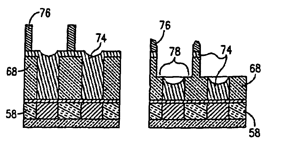
[0009]The instant invention overcomes the problems in the art by providing a fill material or composition which can be applied to via and / or contact holes during damascene processing to provide complete surface coverage while avoiding undue buildup of the etch polymer around the top edge of the holes at the base of the trench of the damascene structure.

Problems solved by technology

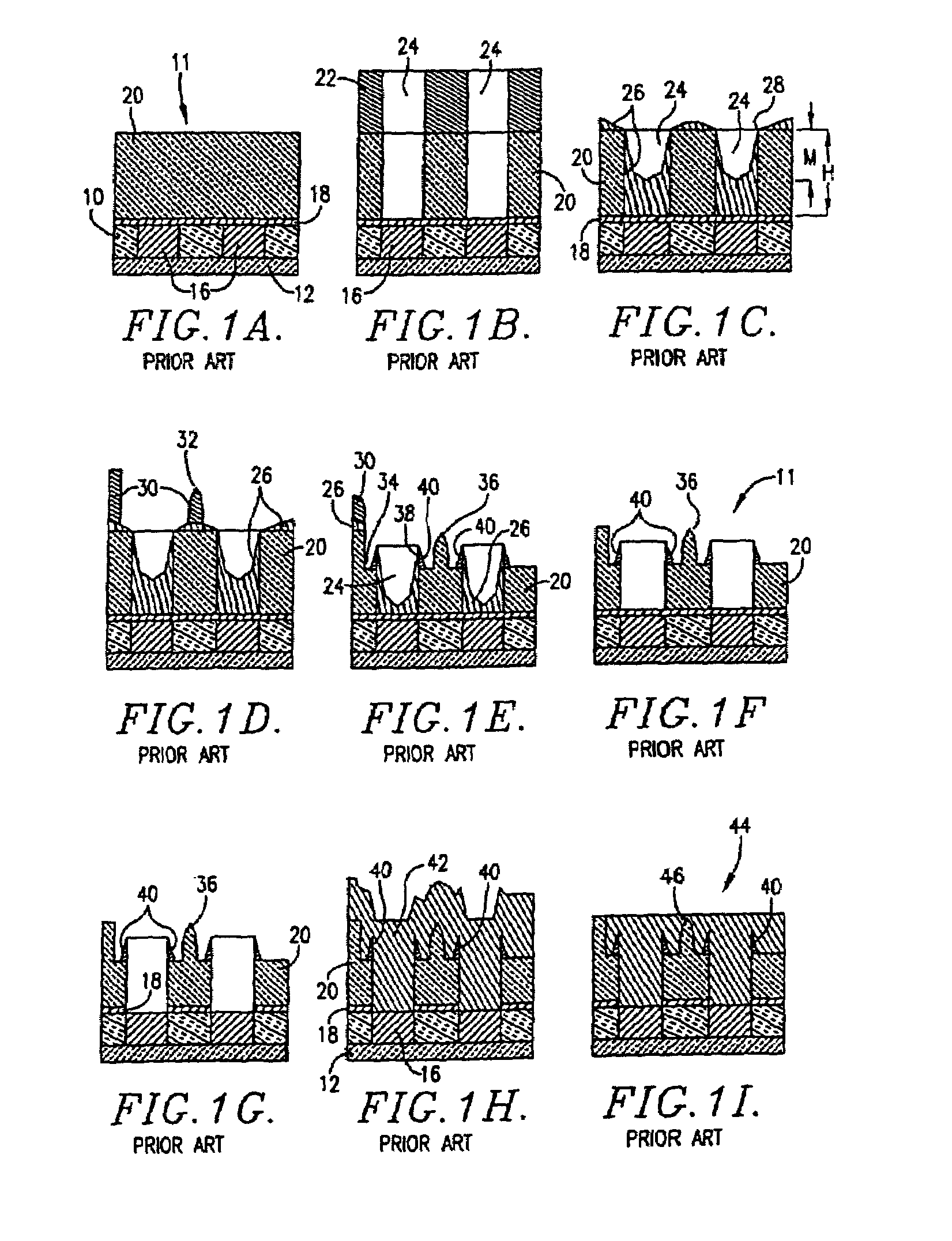
Other problems with the prior art materials is that the cured material forms a steep meniscus (the meniscus height being represented by “M” in FIG. 1C), and the etch rate of the BARC material 26 is slower than that of the dielectric layer 20.
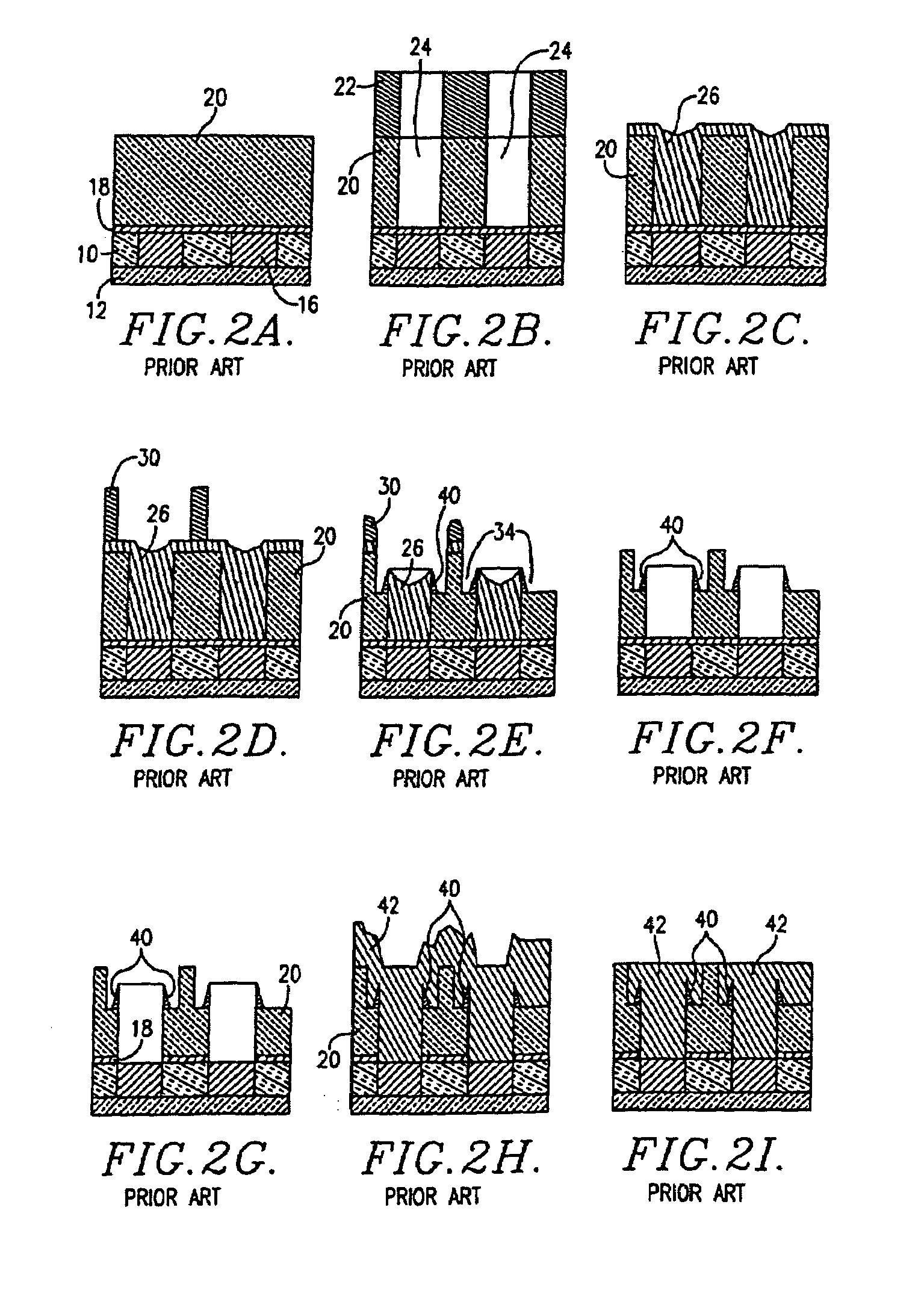
However, conventional BARC material stripping compositions will not remove the polymer 40, and the processes that do remove the polymer 40 tend to attack the dielectric layer 20 and / or protective barrier layer 18.
Furthermore, the buildup of the polymer 40 will cause increased stress in the metal around the polymer 40, thus occasionally leading to the cracking of the metal around the holes 24 and / or trenches 34 resulting in defects in the final circuit.
Again, this leads to higher resistivities and metal stress around the polymer buildup.
Another problem with using prior art BARC materials in a conformal fashion is that the bottom surfaces 52 of the holes 24 often do not have sufficient protection from the etch gas during the etching process.
This in turn will lead to high via or contact resistance and / or complete failure of the interconnect at point 54 (FIG. 3I) after via or contact dual damascene metallization.

Method used


Image

  • Fill material for dual damascene processes
  • Fill material for dual damascene processes
  • Fill material for dual damascene processes

Examples


example 1

1. Copolymer Syntheses

[0107]Using a mantle for heating, the instant reaction was carried out in a three liter, 4-necked flask equipped with a mechanical stirring rod, thermometer, nitrogen inlet plus thermocouple, and a condenser having a nitrogen outlet. Under ambient conditions, the following compounds were charged: 13.59 g of glycidyl methacrylate; 25.25 g of hydroxyl propyl mrethacrylate; 1.17 g of 2,2′-azobisisobutyronitrile; and 1.17 g of 1-dodecanethiol in 158.83 g of PGME. The resulting solution was stirred under nitrogen for 15 minutes to remove oxygen, followed by stirring under nitrogen for 24 hours at 70° C. The heat and nitrogen were turned off, and the reaction mixture was allowed to cool to room temperature.

2. Mother Liquor Syntheses

[0108]Using a mantle for heating, the instant reaction was carried out in a three liter, 4-necked flask equipped with a mechanical stirring rod, thermometer, nitrogen inlet plus thermocouple, and a condenser having a nitrogen outlet. Under...

example 2

Preparation of Full Fill Via or Contact Fill Material

[0109]A via or contact fill material was prepared by mixing 27.62% by weight of the mother liquor prepared in Part 2 of Example 1 with 1.73% by weight Cymel 303LF (cross-linking material available from Cytech Industries, Inc.), 27.35% of PGMEA, and 43.3% by weight of PGME. The mixture was stirred for about 1 hour to give a clear solution after which it was exchanged for 15 hours with 7.24% (based on the weight of the mixture) of 650C exchange resin. The resulting mixture was then filtered through 2×0.1 μm (absolute) end-point filters. This material was coated onto two silicon wafers at a spin speed of 2500 rpm for 60 seconds followed by baking at 160° C. for 1 minute and then a 215° C. bake for 90 seconds. The resulting film had a thickness of approximately 1560 Å.

[0110]This composition was then applied by spin coating to two silicon wafers. The via fill material was static applied then ramped with an acceleration of 20,000 rpm / se...

example 3

Preparation of Partial Fill Via or Contact Fill Material

[0112]The material prepared above in Example 2 was diluted with PGME and PGMEA to produce a via or contact fill material which would provide a film of about 550–600 Å. This fill material was applied to two silicon wafers at a spin speed of 2500 rpm for 60 seconds, followed by a 160° C. bake for 1 minute and a 215° C. bake for 60 seconds to form a film having a thickness of about 590 Å, confirming that the material was properly diluted.

[0113]The diluted fill material was then spin-coated onto two silicon wafers with static application followed by an acceleration of 20,000 rpm / second to 2500 rpm which was held for 60 seconds. Both wafers were pre-baked at 160° C. for 60 seconds in contact hotplate mode. The thicknesses of the films on wafers 1 and 2 were 639 Å and 644 Å, respectively. The pre-bake thermal stability test was conducted on wafer 1. The film thickness after stripping was 0 Å. The film remained completely soluble afte...


PUM


Abstract

An improved via and contact hole fill composition and method for using the composition in the dual damascene production of circuits is provided. Broadly, the fill compositions include a quantity of solid components including a polymer binder and a solvent system for the solid components. The boiling point of the solvent system is less than the cross-linking temperature of the composition. Preferred solvents for use in the solvent system include those selected from the group consisting of alcohols, ethers, glycol ethers, amides, ketones, and mixtures thereof. Preferred polymer binders are those having an aliphatic backbone and a molecular weight of less than about 80,000, with polyesters being particularly preferred. In use, the fill composition is applied to the substrate surfaces forming the contact or via holes as well as to the substrate surfaces surrounding the holes, followed by heating to the composition reflow temperature so as to cause the composition to uniformly flow into and cover the hole-forming surfaces and substrate surfaces. The composition is then cured, and the remainder of the dual damascene process is carried out.

Description

RELATED APPLICATION[0001]This application is a continuation of U.S. patent application Ser. No. 10 / 366,963, filed Feb. 14, 2003, now abandoned and incorporated by reference herein, which is a continuation of U.S. patent application Ser. No. 09 / 966,208, filed Sep. 27, 2001, now abandoned and incorporated by reference herein, which is a continuation of U.S. patent application Ser. No. 09 / 460,162, filed Dec. 13, 1999, now abandoned and incorporated by reference herein, which is a divisional of U.S. patent application Ser. No. 09 / 383,785, filed Aug. 26, 1999, now abandoned and incorporated by reference herein.BACKGROUND OF THE INVENTION[0002]1. Field of the Invention[0003]The present invention is broadly concerned with fill compositions and methods useful for protecting the surfaces forming the contact and via holes during dual damascene processes for the production of integrated circuits. More particularly, the compositions of the invention comprise a quantity of solid cross-linkable c...

Claims


Application Information

Patent Timeline
IPC IPC(8): H01L21/4763H01L21/302H01L21/3065H01L21/312H01L21/3205H01L21/768
CPCH01L21/312H01L21/76808Y10T428/24802Y10T428/12556H01L21/02118H01L21/02282H01L21/28
Inventor LAMB, III, JAMES E.SHAO, XIE
Owner BREWER SCI
Learn More