Method for producing an electronic or electrical component with a plastic-passivated surface

Inactive Publication Date: 2006-04-11
CONTINENTAL AUTOMOTIVE GMBH
View PDF23 Cites 13 Cited by
  • Summary
  • Abstract
  • Description
  • Claims
  • Application Information

AI Technical Summary

Benefits of technology

[0019]If a device is used which exerts a pressure on the body, which pressure is directed onto the surface of the actuator from the outside, then the interspaces between the actuator and the body are filled with material with the aid of the fluidity of the plastic. The device used here is a press tool, for example. During the compression process, the free-flowing plastic functions as the medium of pressure transmission. This means that the same pressure prevails everywhere in the plastic at any given time of the compression process. In the basis of this quasi-isostatic application of pressure, the uniform encapsulating and the self-centering of the actuator are possible in a simple fashion. The cross-linking of the plastic occurs after or during the compression process in a conventional manner; for example, by raising the temperature or by exposure.
[0021]It has proven advantageous if the device in which the plastic body for producing the contact between body and actuator is located has at least one drain opening for excess plastic material. Together with the fluidity of the plastic, possible length tolerances of the actuator can be easily compensated.
[0029]Subsequent to the molding process, the plastic body can be constructed of at least two individual parts, which yield the actual plastic body when joined. For example, the body consists of two half-shells in which the components can be placed easily. In the passivation process, the two half-shells are joined into a single fixedly connected protective casing. Given the utilization of multipartite plastic bodies, electrotechnical components of complicated construction can also be passivated easily and gently.
[0030]It has proven particularly advantageous if the same device is used for the molding of the plastic body and for the passivation of the component. The process conditions for the production of a piezoactuator arrangement can thereby be optimally adapted to the cooperation of the molding of the plastic body with the passivation of the surface of the component.
[0031]Besides the advantages described above, the following should be noted with respect to the invention. Specifically, the automation of the continuous passivation and of the encapsulating of an electronic or electrical component is easily possible. By separating the production of the plastic body and the passivation of the component, it is possible to preproduce the body cost-effectively; for example, in an injection molding process. It is possible to tailor the plastic ductility and the dimensional stability of the plastic, as well as the buildup of plastic component, to the processing process, and so to optimize them. The tools that are necessary for the processing (e.g. injection molding for producing the plastic body and a compression process in the passivation of the component) are relatively easy to realize. Arbitrary plastics can be employed. The described method is cost-effective.

Problems solved by technology

The body can also have a complicated construction.

Method used


Image

  • Method for producing an electronic or electrical component with a plastic-passivated surface
  • Method for producing an electronic or electrical component with a plastic-passivated surface
  • Method for producing an electronic or electrical component with a plastic-passivated surface

Examples


Embodiment Construction

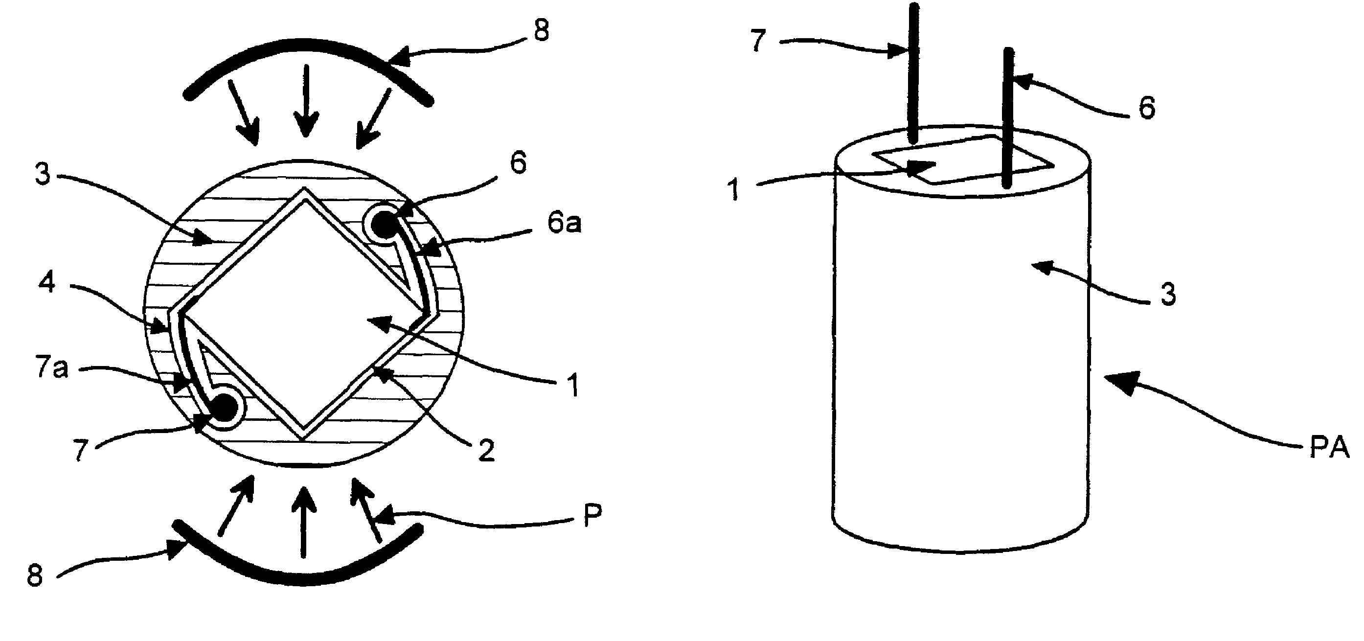
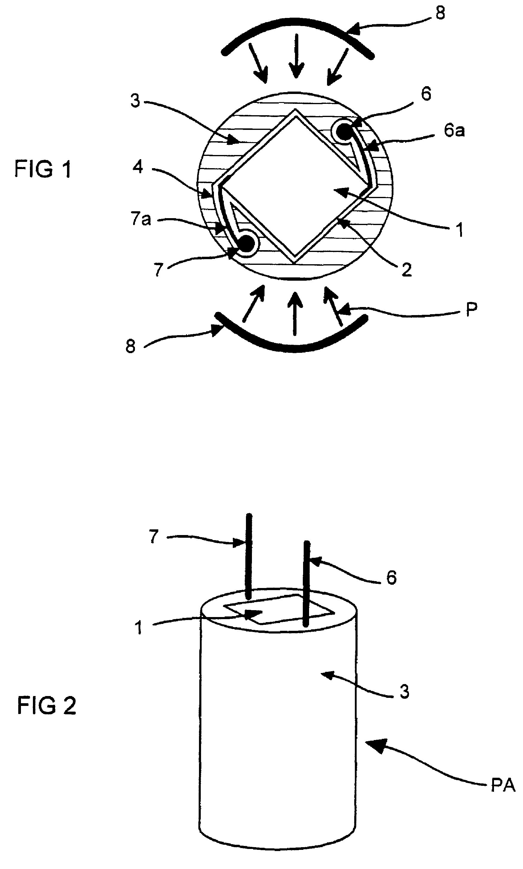
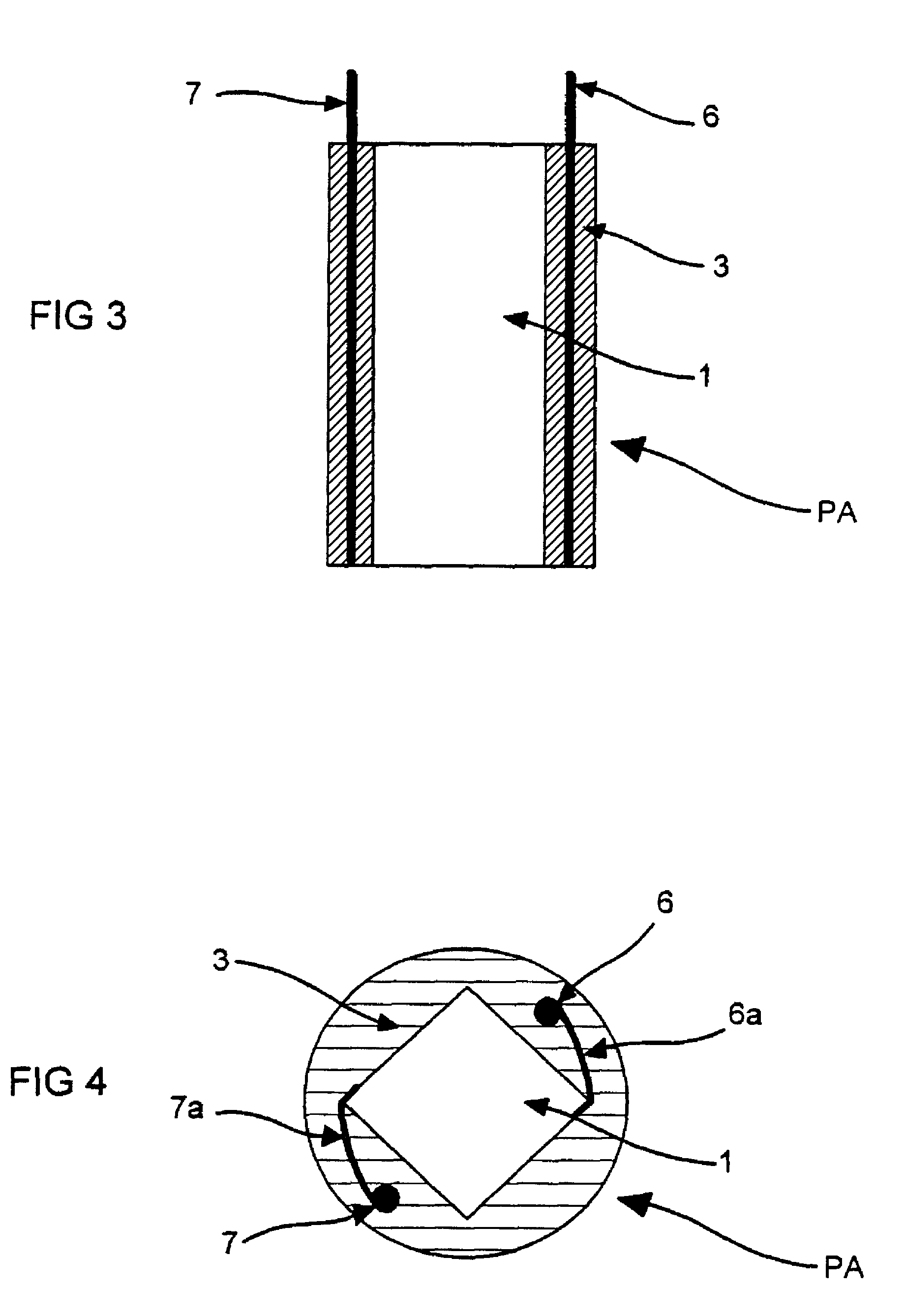
[0062]The piezoactuator arrangement PA (see FIG. 2) consists of a piezoactuator 1, which is connected via contact lugs 6a and 7a and to electrical terminals 6 and 7, as well as a plastic body 3 (see FIG. 1).

[0063]The piezoactuator arrangement PA is produced in two subprocesses. In a first step, the plastic body 3 is preproduced in a molding process. In the second step, the passivation and simultaneous encapsulation of the piezoactuator with its electrical terminals occur. The same device is used in the preproduction of the plastic body and the passivation of the actuator.

[0064]The plastic body 3 is produced in an injection molding process, for example. As another essential feature, besides a drain opening for excess plastic material, the device used comprises the shape of the surface 2 of the actuator 1. A plastic body 3 with a hollow space 5 (see FIG. 7) is thereby obtained in the molding process, the inner surface 4 of which comprises the surface 2 of the actuator 1, in inverse fo...


PUM

PropertyMeasurementUnit
Pressureaaaaaaaaaa
Viscosityaaaaaaaaaa
Adhesion strengthaaaaaaaaaa

Abstract

A simple method for passivation of a component is presented which is particularly suitable for processing high-viscosity plastics. The component is arranged in a preproduced plastic body and is connected to the body. This method is proposed for the production of a piezoactuator arrangement, which is utilized for controlling injection valves in internal-combustion engines. The plastic consists of solid silicone and / or fluorinated silicone elastomer.

Description

CROSS-REFERENCE TO RELATED APPLICATIONS[0001]The present application is a division of U.S. Ser. No. 09 / 295,917, now abandoned, filed Apr. 21, 1999.FIELD OF THE INVENTION[0002]The present invention relates generally to methods for producing an electrical or electronic (i.e. “electrotechnical”) component which includes a surface to be passivated with a plastic coating. More specifically, the present invention relates to a method for producing such a component that comprises the steps of providing a plastic body for accommodating and encapsulating the surface of the component, inserting the component into the plastic body and joining the surface of the component to the plastic body by applying pressure to the plastic body.BACKGROUND OF THE INVENTION[0003]It is often necessary to passivate sensitive electronic components such as piezoactuators in order to insulate their surfaces electrically and to protect their surfaces from contamination or mechanical damage. This is achieved among ot...

Claims


Application Information

Patent Timeline
IPC IPC(8): H04R17/00B29C70/72F02M51/06F02M63/00H01L41/053H01L41/083H01M8/02H02N2/04
CPCB29C70/72F02M51/0603H01L41/083H01M8/02H01L41/0533H01L41/23H01L41/0475Y02E60/50Y10T29/4913Y10T29/435Y10T29/49146Y10T29/42Y02P70/50H10N30/883H10N30/875H10N30/50H10N30/02
Inventor SCHUH, CARSTENHEKELE, WILHELM
Owner CONTINENTAL AUTOMOTIVE GMBH
Why Eureka
Try Eureka