Rotary cutting saw
a cutting saw and rotary technology, applied in the direction of gear teeth, manufacturing tools, manufacturing apparatus, etc., can solve the problems of reducing the grooving ability or grooving ability of the cutting saw, disadvantageously expensive for the complication of segment manufacturing,
- Summary
- Abstract
- Description
- Claims
- Application Information
AI Technical Summary
Benefits of technology
Problems solved by technology
Method used
Image

Examples
first embodiment
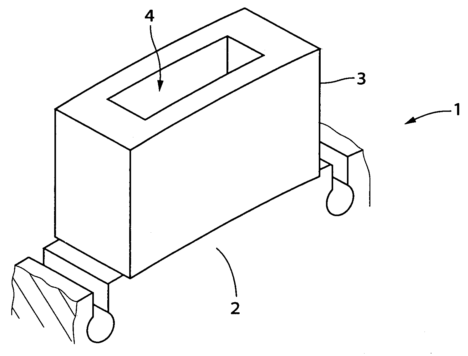
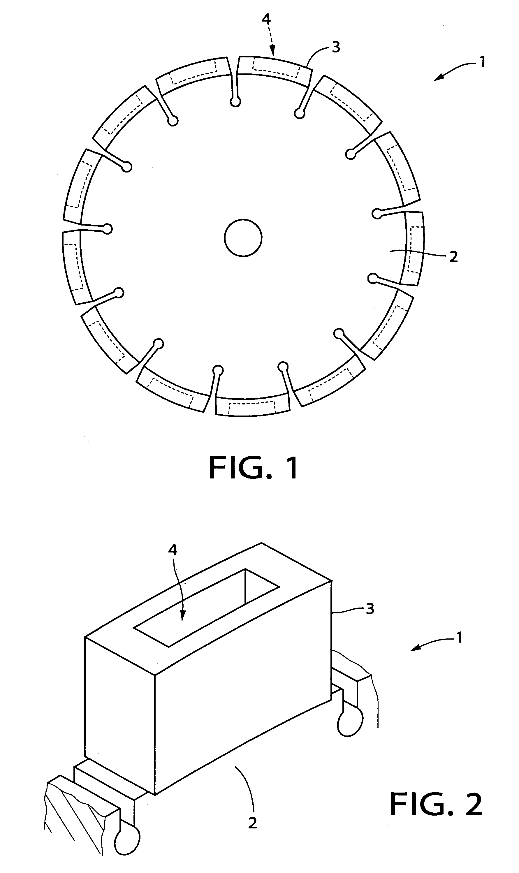
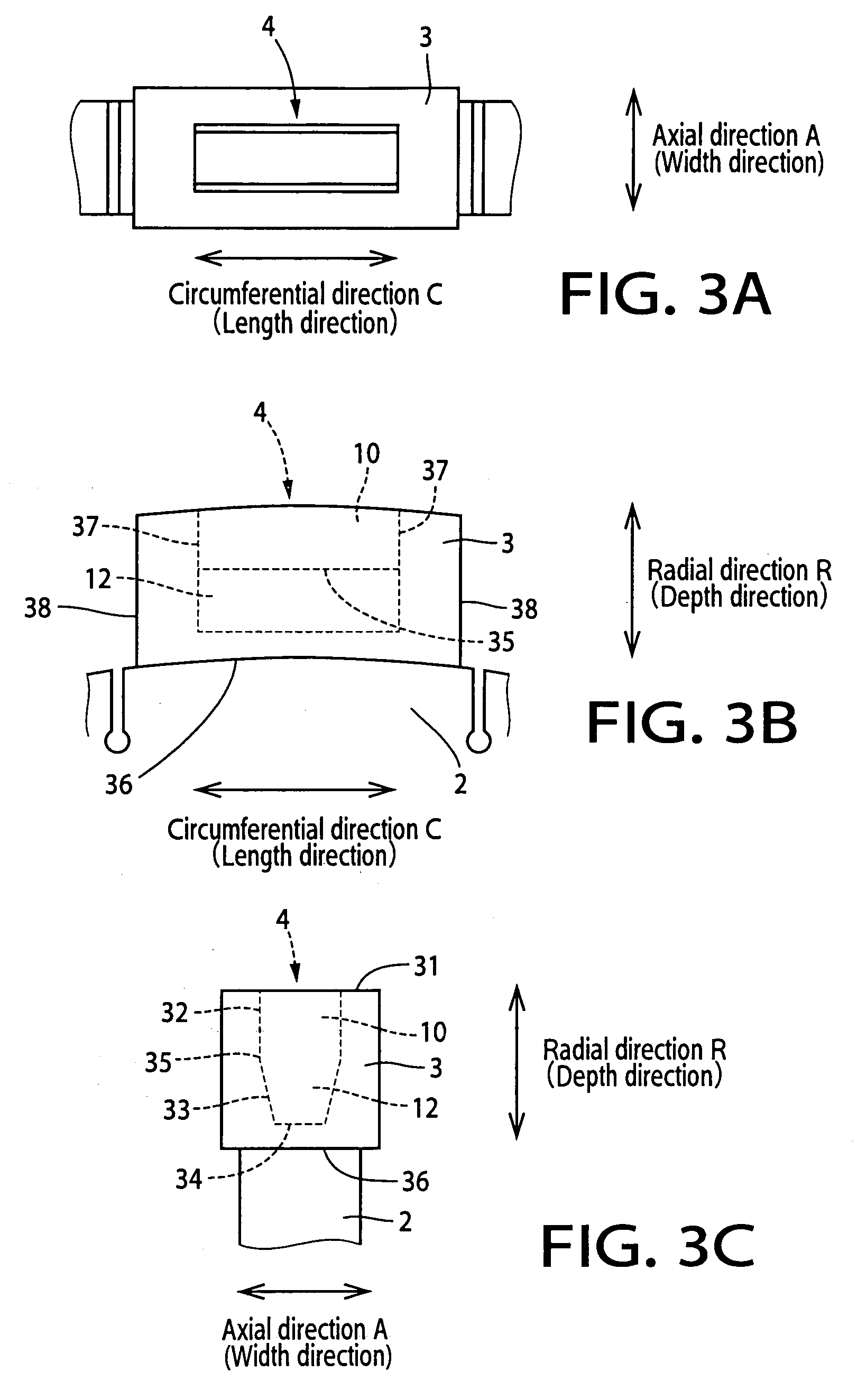
[0048]Hereinafter, there will be described a rotary cutting saw by reference to the drawings. The first embodiment is referred to as follows. In FIGS. 1, 2, 3A, 3B and 3C, the rotary cutting saw 1 is provided with a base disk 2 and a plurality of abrasive segments 3 which are fixed to an outer circumferential surface of the base disk 2 and which have respective outer surfaces, namely, outer circumferential surfaces 31, cooperating with each other to constitute an outer circumferential surface of the rotary cutting saw 1. Each of the abrasive segments 3 has at least one recess 4 opening in the outer surface thereof. Each of the at least one recess 4 has a radially outer portion 10 and a radially inner portion 12 which is located inwardly of the radially outer portion 10 as viewed in a radial direction R of the base disk 2, the radially outer portion 10 has a width that is constant in the radial direction R and the radially inner portion has a width that varies in the radial direction...
second embodiment
[0052]The second embodiment is referred to as follows. In FIGS. 4, 5A, 5B and 5C, the rotary cutting saw 1 is provided with a base disk 2 and a plurality of abrasive segments 3 which are fixed to an outer circumferential surface of the base disk 2 and which have respective outer surfaces, namely, outer circumferential surfaces 31, cooperating with each other to constitute an outer circumferential surface of the rotary cutting saw 1. Each of the abrasive segments 3 has at least one recess 4 opening in the outer surface thereof. Each of the at least one recess 4 has a radially outer portion 10 and a radially inner portion 12 which is located inwardly of the radially outer portion 10 as viewed in a radial direction R of the base disk 2, the radially outer portion 10 has a width that is constant in the radial direction R and the radially inner portion has a width that varies in the radial direction R. The width of each of the radially outer and inner portions 10, 12 is a dimension of ea...
PUM
| Property | Measurement | Unit |
|---|---|---|
| Fraction | aaaaa | aaaaa |
| Fraction | aaaaa | aaaaa |
| Angle | aaaaa | aaaaa |
Abstract
Description
Claims
Application Information
 - R&D
- Intellectual Property
- Life Sciences
- Materials
- Tech Scout
- Unparalleled Data Quality
- Higher Quality Content
- 60% Fewer Hallucinations
Browse by: Latest US Patents, China's latest patents, Technical Efficacy Thesaurus, Application Domain, Technology Topic, Popular Technical Reports.
© 2025 PatSnap. All rights reserved.Legal|Privacy policy|Modern Slavery Act Transparency Statement|Sitemap|About US| Contact US: help@patsnap.com