System and method for quantifying errors in an alternating phase shift mask

Inactive Publication Date: 2006-03-21
POLARIS INNOVATIONS
View PDF24 Cites 4 Cited by
  • Summary
  • Abstract
  • Description
  • Claims
  • Application Information

AI Technical Summary

Benefits of technology

[0027]The present invention provides an inexpensive and effective method and system for detecting aspects relating to the quality of an alternating phase shift mask.

Problems solved by technology

As feature sizes and pitches shrink, however, the resolution of the projection optics begins to limit the quality of the mask pattern.
As a result, the quality and yield of semiconductor devices that are manufactured by this mask are poor.
Although utilizing AltPSM is a powerful solution for improving the photolithographic technique in today's subwavelength industry, it is considered to be more demanding and expensive in comparison with use of a BIM.
There are at least three types of errors that may influence the quality of the AltPSM.
Generally, a phase error may exist if an incorrect material depth is obtained relative to the refractive index of the incident light (for example, if the etched transparent areas 230 in FIG. 2A are etched such that areas are too deep or too shallow).
A third type of error that may occur in a PSM is a transmission error.
However, it can be difficult and cumbersome to detect phase errors and transmission errors with a SEM and the results are often inaccurate.
As described above, since a phase shift is generated by etching into the quartz on the mask, there can be a significant amount of transmission imbalance between the 180-degree areas and the 0-degree areas due to scattering etching processes, etc.
Several methods have been used to compensate for this, however, due to the non-linear behavior of transmission loss error, the compensation is generally non-uniform.
Although AIMS tools can effectively detect mask defects, use of such tools is very complex and expensive.
Moreover, as AIMS tools are applied to detect larger areas of the mask, complicated software is required to calculate the mask patterns, thereby further increasing the cost of employing the AIMS system.
However, for many masking manufacturing processes, it is not necessary to detect large areas of the mask and more particularly, to use expensive detection tools and complicated software to evaluate mask quality.

Method used


Image

  • System and method for quantifying errors in an alternating phase shift mask
  • System and method for quantifying errors in an alternating phase shift mask
  • System and method for quantifying errors in an alternating phase shift mask

Examples


Embodiment Construction

[0053]Hereinafter, preferred embodiments of the present invention will be described in detail with reference to the attached drawings. This invention may be embodied in many different forms and should not be construed as being limited to the embodiments set forth herein.

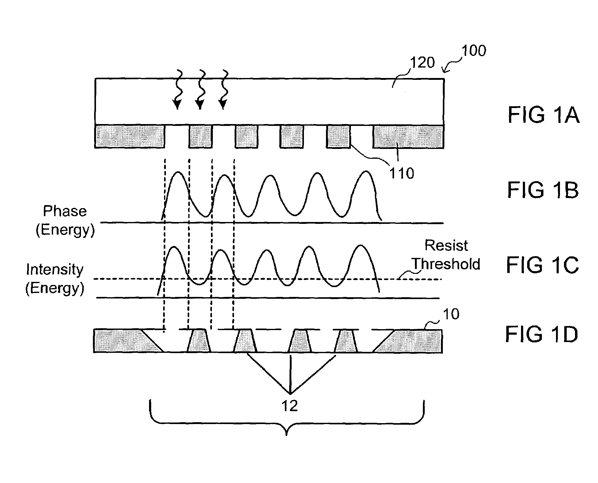
[0054]As described above, any imbalance in phase, transmission or CD in a photolithographic mask results in poor quality wafers after lithography via the mask. The present invention provides a method and system for detecting the phase and transmission balance of a mask such as an alternating phase shift mask.

[0055]In accordance with an embodiment of the present invention, any imbalance of phase and transmission of the mask is detected at the boundary between the 0-degree phase shift and 180-degree phase areas. This detects light intensity at the zeroth order to calculate whether there is any phase offset error occurring at the boundary. If the intensity of the zeroth order at a specific wavelength used in the lithogr...


PUM


Abstract

A method and system for detecting the quality of an alternating phase shift mask having a number of 180-degree phase shift areas alternating with a number of 0-degree phase shift areas is disclosed. In operation, a light source which provides wavelength-adjustable incident lights illuminates the incident lights on the alternating phase shift mask. The light outputs from boundaries between the 0-degree phase shift areas and the 180-degree phase shift areas of the alternating phase shift mask are detected. Relation curves of the wavelength of the incident light and a light intensity of the boundaries are then calculated. Phase errors of the alternating phase shift mask can thus be measured from the relation curves.

Description

BACKGROUND[0001]1. Field of the Invention[0002]The present invention generally relates to a system and method for detecting the quality of an alternating phase shift mask and, more particularly, to a system and method for detecting and quantifying errors in an alternating phase shift mask.[0003]2. Background of the Invention[0004]Photolithography is commonly utilized in the field of semiconductor manufacturing to form features (or patterns) on a wafer substrates. In one type of photolithography, known as “binary intensity mask” (“BIM”) photolithography, a photoresist or mask formed with patterns composed of opaque areas (such as chrome) and transparent areas (such as quartz) is placed above a semiconductor layer where a pattern will be formed, such as an insulating layer or a conductive layer on a semiconductor substrate. As illustrated in FIG. 1, a mask 100, together with a substrate underlayer 10, is exposed to radiation light, which may include x-ray, ultraviolet rays or other ra...

Claims


Application Information

Patent Timeline
IPC IPC(8): G01N21/00G01N21/956G03F1/00G01N21/41G01N21/47
CPCG01N21/41G01N21/4788G01N21/956G01N2021/95676G01N2021/4173
Inventor BUTT, SHAHIDZAIDI, SHOAIB
Owner POLARIS INNOVATIONS
Why Eureka
Try Eureka