
Filtering method of a colloidal solution

a filtering method and colloidal solution technology, applied in the direction of water/sewage treatment by ion exchange, differential sedimentation, treatment water, etc., can solve the problems of large amount of slurry diluted by pure water discharge, environmental problems, wastewater treatment technology, etc., and achieve the effect of quick loading and difficult processing of large amounts of wastewater

Inactive Publication Date: 2006-03-21
SANYO ELECTRIC CO LTD
View PDF11 Cites 19 Cited by
  • Summary
  • Abstract
  • Description
  • Claims
  • Application Information

AI Technical Summary

Benefits of technology

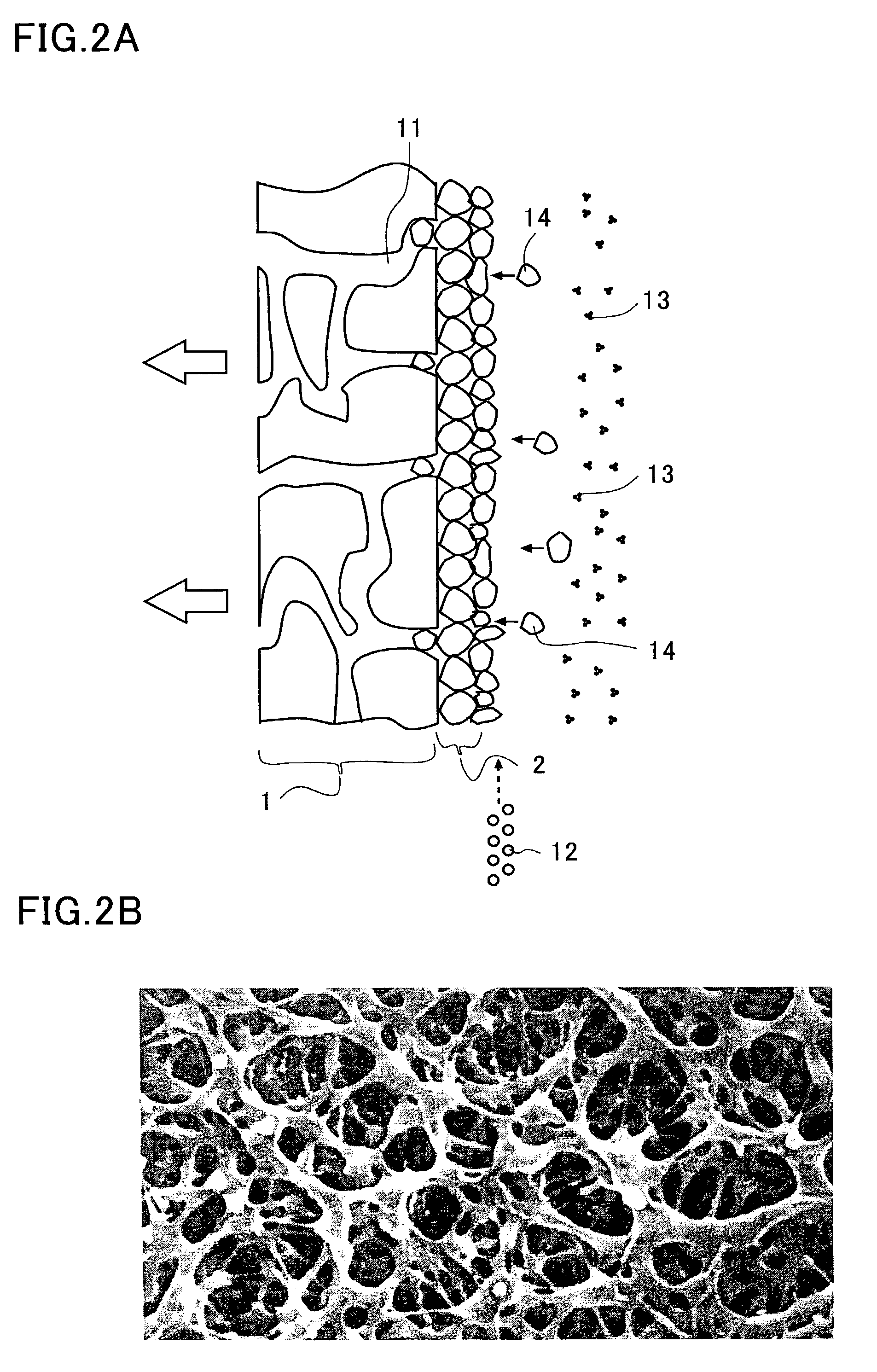
[0138]This invention provides a method of filtering substances in colloidal solutions without using a filter membrane having pores smaller than 0.15 μm, but rather forming a filter of a gel membrane using coagulants or pH adjusters that help promote gelation. Further, an extended use of the second filter is achieved by minimizing the probability of clogging with the selected optimum formation condition of the second filter and a constant filtration rate. It is easy to regenerate the second filter because the gel accumulated on the surface of the second filter can be removed by its own weight by simply stopping the suctioning of the pump. This makes it possible to conduct the cycle of filtration, regeneration and refilteration repeatedly. Thus making this filtration process continues for an extremely long time. Further, the reverse washing required in conventional filtration method is not necessary because the gel accumulated on the surface of the second filter can be removed in the regeneration of the second filter by the force that brings back the filters that has been bulging outward by simply stopping the suction of the pump. The removal of the gel can be also promoted by applying the rising force and bursting force of the air bubbles to the surface of the second filter by increasing the rate of air bubbles during the regeneration.

Problems solved by technology

However, due to the cost of filtration and associated running costs, it is very difficult to adopt these devices, which results in environmental problems.
As can be understood from the above, wastewater treatment technology is a very important issue from the standpoint of both environmental protection and resource recycling.
Thus, a large amount of slurry diluted by pure water is discharged when the CMP device is used.
It is very difficult to estimate the right amount of chemicals for a complete chemical reaction, thus an excessive amount of chemicals is loaded and the chemicals remain unconsumed at the end.
On the other hand, if the amount of chemicals is not sufficient, some substances remain in the solution.
If such wastewater is intended to be reused, the chemicals remaining in the filtered liquid present a problem that they cannot be used for any application that prohibits inclusion of chemicals.
Moreover, some of the flocks remain floating without precipitating, and are more likely to flow out of the tank, and it is difficult to collect all of them.
Thus, the system is subject to problems such as a large system size, high initial cost, difficulty in water reuse and high running cost due to the use of chemicals.
However, since filtration device 203 requires four filters F that have a short life, it is necessary to replace four of these expensive filters, each costing approximately 500,000 yen, at least once a year.
Moreover, pump 202 placed ahead of filtration device 203 tends to develop clogging, causing a high load on the motor, since the filter F is based on a pressurized type filtration method.
In summary, the problem with this method is an extremely high running cost due to high electric power consumption and replacements of the pump P and the filter F.
Furthermore, CMP consumes an amount of wastewater much higher than the dicing process.
Therefore, if the slurry including such fine particles is filtered using a filter, the pores of the filter become very quickly loaded with abrasive grinding stones, causing clogging often and making it difficult to process a large amount of wastewater.
As can be seen from the above explanation, the filtration device for wastewater used for removing substances that affect the global environment or for reusing filtered fluids or separated substances is often a substantial system of a high initial and running costs.
Therefore, these conventional wastewater treatment devices are hardly useful in practical applications.
However, since such a filter does not exist, a common knowledge has been that it is impossible to filter such a liquid.

Method used


Image

  • Filtering method of a colloidal solution
  • Filtering method of a colloidal solution
  • Filtering method of a colloidal solution

Examples


Embodiment Construction

[0054]First, the terms used in describing this invention are described. A colloidal solution is a solution in which fine particles having diameters ranging from 1 nm to 1 μm are dispersed. These particles are subject to the Brownian motion and are capable of passing through regular paper filters but not semipermeable membranes. The slow coagulation speed of the colloidal particles is due to the electrostatic forces between the particles, which prevent the particles from contacting.

[0055]The term sol is used as nearly synonymous with a colloidal solution. Different from a gel, sol is dispersed in a liquid, presents fluidity, and is subject to the Brownian motion.

[0056]A gel is a state where colloidal particles have lost mobility and become rigid. For example, agar and gelatin become sol when they are dissolved in warm water, but lose fluidity and become a gel when they are cooled. Gels can be divided into hydrogel that contains a large amount of fluid and xerogel that is dry.

[0057]A ...


PUM

PropertyMeasurementUnit
Thicknessaaaaaaaaaa
Pressureaaaaaaaaaa

Abstract

A filtering method is directed to a wastewater of CMP process, which includes sub-micrometer particles suspended as colloid. The wastewater is filtered by a gel membrane formed on a surface of plastic filter. A coagulant or a pH adjuster is added to the wastewater so that the sub-micrometer particles are coagulated to form the gel membrane.

Description

BACKGROUND OF THE INVENTION[0001]1. Field of the Invention[0002]The invention relates to a filtration method of colloid solution, specifically to a filtration method of a colloidal solution containing very fine substances having diameters less than 0.15 μm.[0003]2. Description of the Related Art[0004]It is critical for corporations operating in the 21 st century to reduce industrial wastes, to classify industrial wastes so that wastes can be recycled and not to release industrial wastes into the environment from an ecological standpoint.[0005]Although various terms are employed to denote aqueous wastes such as sewage, wastewater and wastes, all aqueous and chemical solutions containing substances that require removal will hereinafter be generally called wastewater. The substances are generally removed from wastewater by expensive filtration devices so that the wastewater can be reused and that the separated substances or filter out substances are treated as industrial wastes. Water ...

Claims


Application Information

Patent Timeline
IPC IPC(8): C02F1/52B01D37/02B01D61/16B01D69/14C02F1/00C02F1/44C02F1/46C02F1/66C02F1/76C02F9/00C02F11/00C02F11/12
CPCB01D61/16B01D61/147C02F1/444C02F1/5245C02F1/66B01D69/14B01D61/145B01D2311/04C02F1/001C02F1/76C02F9/00C02F2101/16C02F2103/346C02F2303/16Y10S210/903C02F1/52C02F1/44B01D2311/12B01D2311/18B01D2311/2642B01D2311/14B01D21/01C02F1/00H01L21/304B01D24/00
Inventor UMEZAWA, HIROYUKIISEKI, MASAHIROTSUIHIJI, MOTOYUKIIINUMA, HIROFUMI
Owner SANYO ELECTRIC CO LTD
Learn More