Projection optical system and projecting apparatus provided with same

a projecting apparatus and optical system technology, applied in the field of projecting optical systems, can solve the problems of insufficient adjustment of the air equivalent distance between the first lens unit on the enlargement side, the second lens unit on the reduction side of the optical path bending member, and the inability to avoid cost increase, so as to achieve the effect of suppressing cost increase and reducing thickness of the projecting apparatus

Inactive Publication Date: 2006-03-14
KONICA MINOLTA OPTO
View PDF7 Cites 3 Cited by
  • Summary
  • Abstract
  • Description
  • Claims
  • Application Information

AI Technical Summary

Benefits of technology

[0011]The present invention is made to solve the above-mentioned problem, and an object thereof is to provide a projection optical system with which the thickness of a projecting apparatus can be reduced while a cost increase is suppressed, by appropriately setting the space for disposing the optical path bending member, and the projecting apparatus.
[0014]Therefore, by designing the projection optical system so that the condition (1) is fulfilled and appropriately setting the space for disposing the optical path bending member, the thickness of the projecting apparatus can be reduced while an increase in the cost of the projection optical system is suppressed.
[0015]Moreover, a projecting apparatus according to the present invention comprises the above-described projection optical system and a display device that supplies the projection optical system with light corresponding to a display image. With this structure, the thickness of the projecting apparatus can be reduced while an increase in the overall cost of the apparatus is suppressed.

Problems solved by technology

However, in the rear projector of the Patent Document 1, the space for disposing the optical path bending member, that is, the air equivalent distance between a first lens unit on the enlargement side (screen side) of the optical path bending member and a second lens unit on the reduction side of the optical path bending member is not appropriately set.
Consequently, there are cases where a cost increase cannot be avoided when the thickness of the rear projector is reduced, so that the reduction in the thickness of the rear projector is hindered.
Consequently, the cost of the first lens unit increases.
Consequently, the cost of the projection optical system increases by the amount necessitated by such processing.

Method used


Image

  • Projection optical system and projecting apparatus provided with same
  • Projection optical system and projecting apparatus provided with same
  • Projection optical system and projecting apparatus provided with same

Examples


first embodiment

[0041]A first embodiment of the present invention will be described with reference to the drawings as follows:

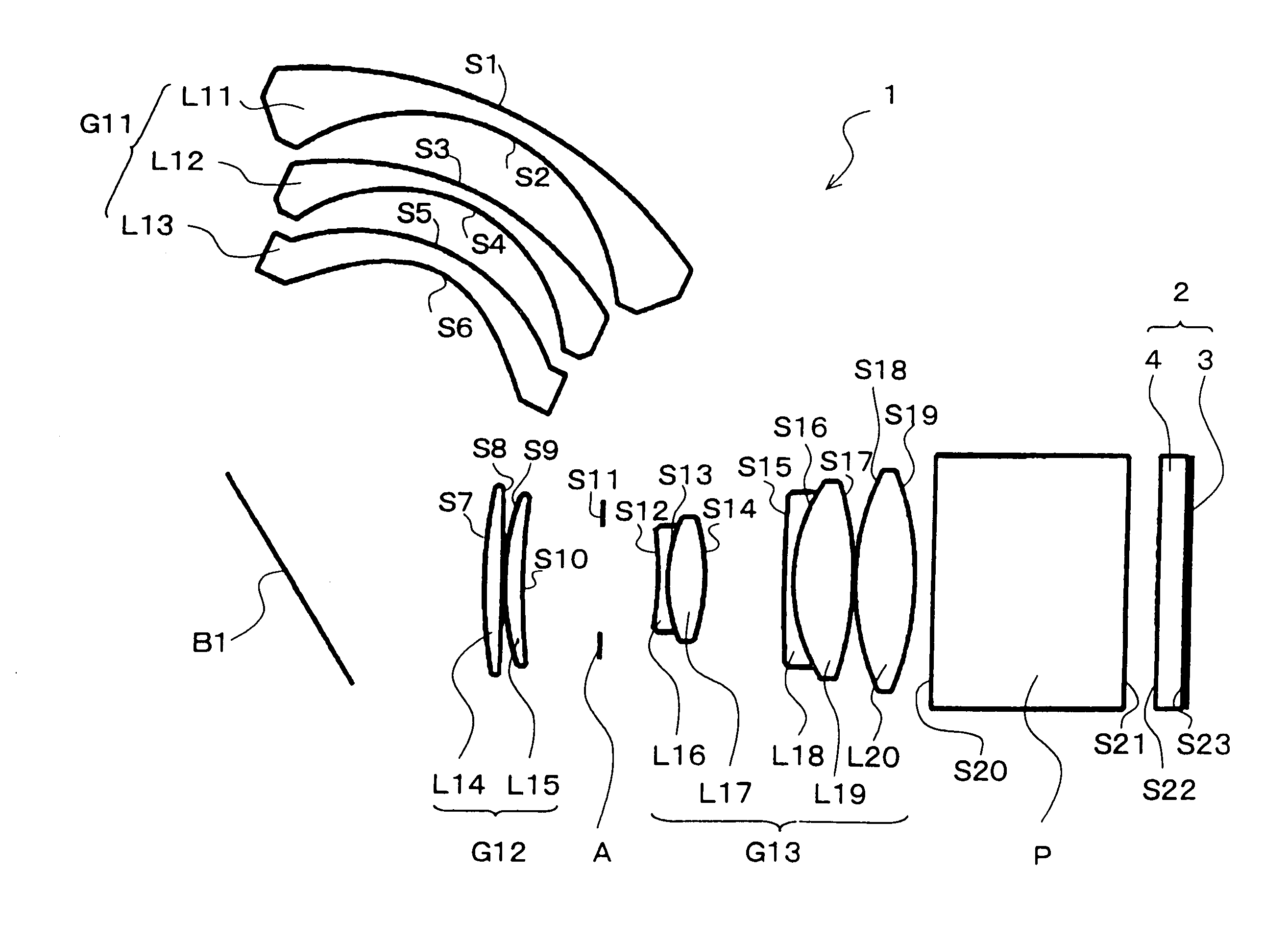
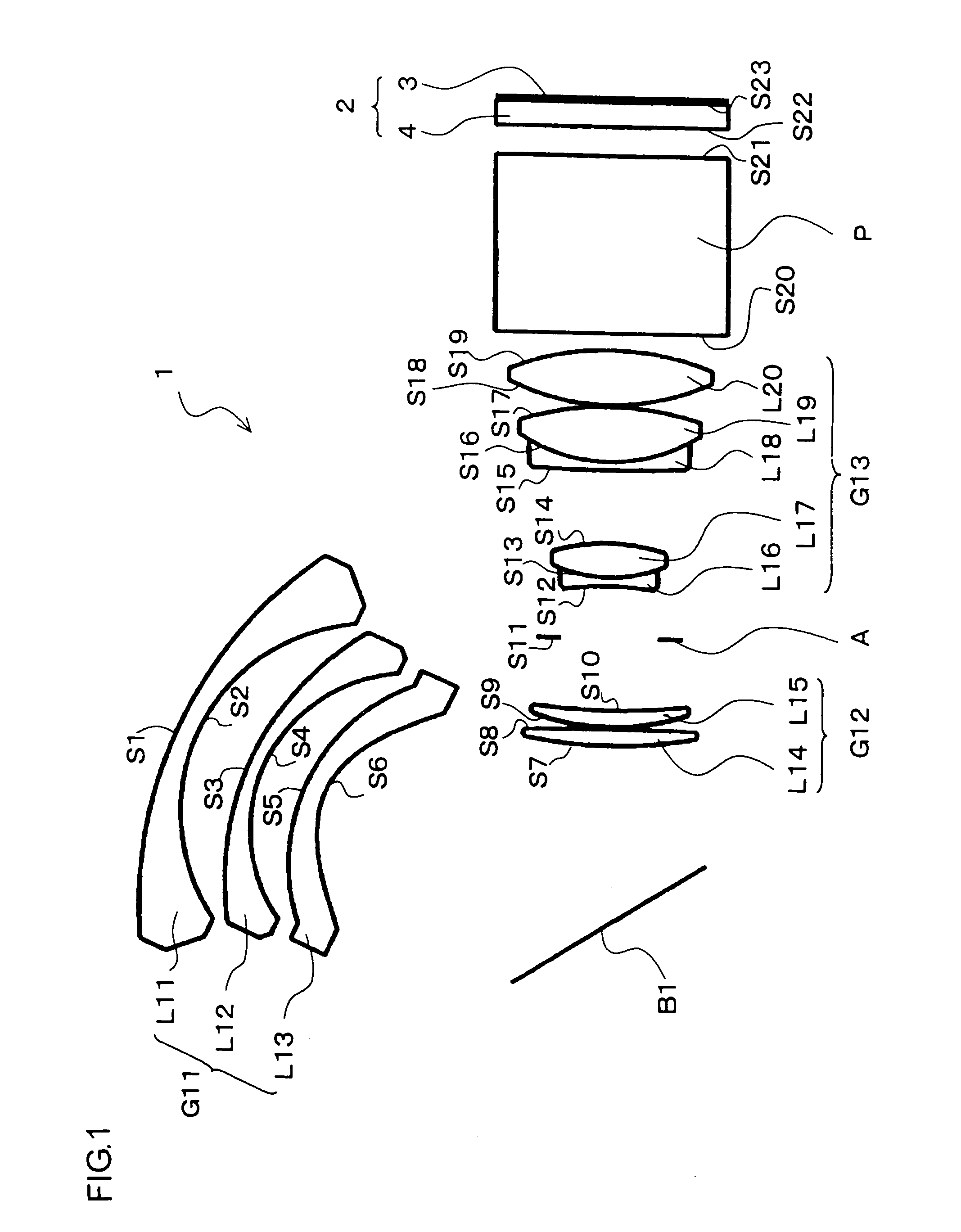
[0042]FIG. 1 is an explanatory view showing the schematic structure of a projecting apparatus according to the present embodiment. This projecting apparatus comprises a projection optical system 1 and a DMD device 2.

[0043]The DMD device 2 comprises a DMD 3 and a cover glass 4 disposed in front (on the light reflecting side) of the DMD 3. The DMD 3 comprises micromirrors that are turned on and off in accordance with the image data of the display image which micromirrors are arranged in a matrix. The mirrors of the DMD 3 each correspond to one pixel. By changing the angle of inclination of each mirror in accordance with the image data, light from the light source (not shown) can be made selectively incident on the projection optical system 1 for each pixel. Therefore, it can be said that the DMD 3 constitutes a display device that supplies the projection optical system 1 with ...

first example

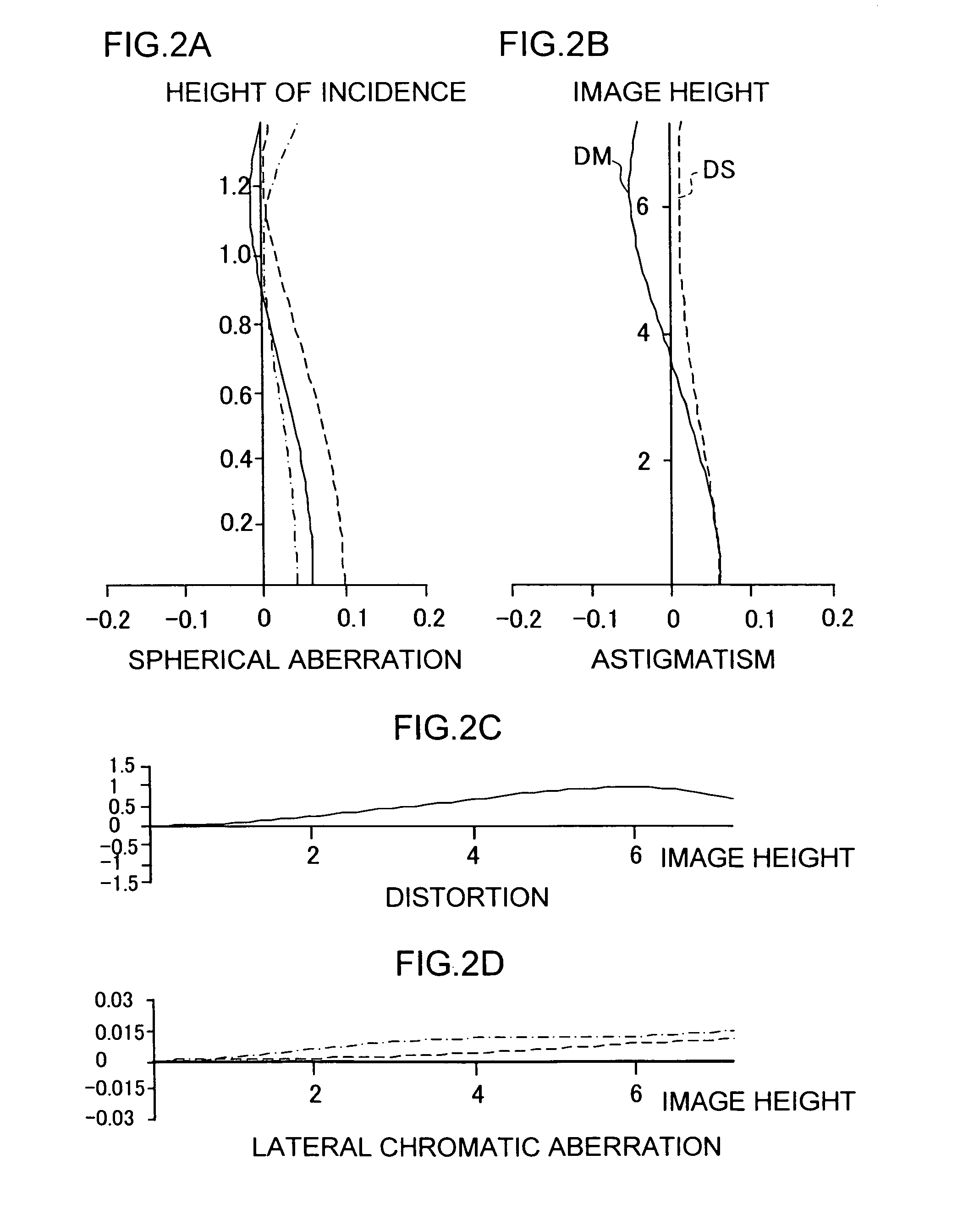
[0077]Table 1 shows the construction data of the projection optical system 1 according to the present example. In the present example, the F number is 2.5, the angle of view (2ω) is 90.0 degrees, and the overall focal length FL of the projection optical system 1 is 7.14 mm. Moreover, the projection distance (the axial distance from the enlargement side surface of the lens element L11 to the screen surface (projected surface)) is 701 mm.

[0078]

TABLE 1SCRTNdVd151.98472.30001.603160.70223.18317.18101.0000335.32811.70001.658450.90419.17105.37871.0000523.40292.50001.530555.72611.198558.02871.0000755.05921.99671.717429.508−400.16400.21001.0000926.54602.10671.620036.301072.43718.80281.000011APR6.42531.000012−33.19241.00001.806133.301316.52574.12741.487570.4014−21.26618.79531.000015157.22301.00001.806133.301619.16456.75421.487570.4017−33.58450.20001.00001827.12276.71401.487570.4019−31.09172.00831.000020INF21.41001.516864.2021INF3.50001.000022INF3.00001.508561.1923INF0.50001.0000

[0079]In Tabl...

second embodiment

[0093]A second embodiment of the present invention will be described with reference to the drawings as follows. The same structures as those of the first embodiment are denoted by the same reference numerals, and descriptions thereof are omitted.

[0094]FIG. 3 is an explanatory view showing the schematic structure of a projecting apparatus according to the present embodiment. In the projecting apparatus of the present embodiment, in the projection optical system 1 of the first embodiment, the lens element L16 and the lens element L17 of the third lens unit G13 are not cemented together, and the parameters (the radius of curvature, the axial distance, the refractive index and the Abbe number) of each lens element are optimized accordingly. Except this, the basic structure is similar to that of the first embodiment.

[0095]In the present embodiment, the projection optical system 1 is also designed so that the conditions (1) to (4) shown in the first embodiment are fulfilled. The detailed ...


PUM


Abstract

A projection optical system includes from the enlargement side a first lens unit, a mirror which is an optical path bending member, a second lens unit, and a third lens unit. The projection optical system is designed so that a condition (1), 5.5<T12 / FL<12.0, is fulfilled. Here, T12 is the air equivalent distance between the first lens unit and the second lens unit, and FL is the overall focal length of the projection optical system. By fulfilling the condition (1), it is unnecessary that the diameter of the first lens unit be extremely large. It is also unnecessary to change the lens shape to prevent interference between the first lens unit and the second lens units, so that an increase in the cost of the projection optical system can be suppressed.

Description

[0001]This application is based on Patent Application No. 2004-191256 filed in Japan on Jun. 29, 2004, and Patent Application No. 2004-309850 filed in Japan on Oct. 25, 2004, the entire contents of which are hereby incorporated by reference.BACKGROUND OF THE INVENTION[0002]1. Field of the Invention[0003]The present invention relates to a projection optical system that is used mainly for a rear projector or the like using a DMD (digital micromirror device; made of Texas Instruments Incorporated of the United States), an LCD (liquid crystal display) or the like as a display device and has a long back focal distance and whose reduction side is substantially telecentric, and a projecting apparatus having the projection optical system.[0004]2. Description of the Prior Art[0005]Recently, high-performance and low-priced rear projectors having a DMD or an LCD as a display device have been spreading. By installing such a rear projector, for example, in a home, it is possible to see images re...

Claims


Application Information

Patent Timeline
Patent Type & Authority Patents(United States)
IPC IPC(8): G02B3/00G02B13/16
CPCG02B13/16
Inventor MASUBUCHI, TOMOKAZUHAYASHI, KOHTAROSAWAMURA, SHIGERU
Owner KONICA MINOLTA OPTO
Why Eureka
Try Eureka