
Device and method for the detection of an analyte utilizing mesoscale flow systems

a flow system and flow device technology, applied in the field of analytical methods and apparatus, can solve the problems of not fully exploiting the potential of mesoscale structures in the life sciences, not producing data associated with an analytical device, and not fully exploring the potential of using mesoscale devices. , to achieve the effect of preventing contamination and ensuring sterilization

Inactive Publication Date: 2006-02-28
THE TRUSTEES OF THE UNIV OF PENNSYLVANIA
View PDF28 Cites 174 Cited by
  • Summary
  • Abstract
  • Description
  • Claims
  • Application Information

AI Technical Summary

Benefits of technology

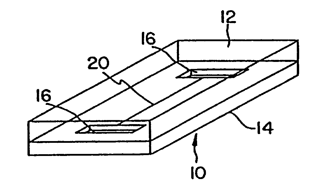
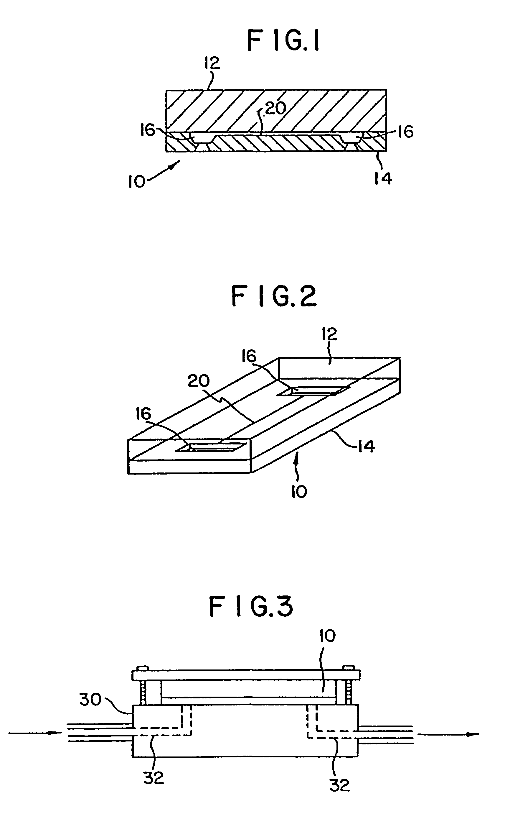
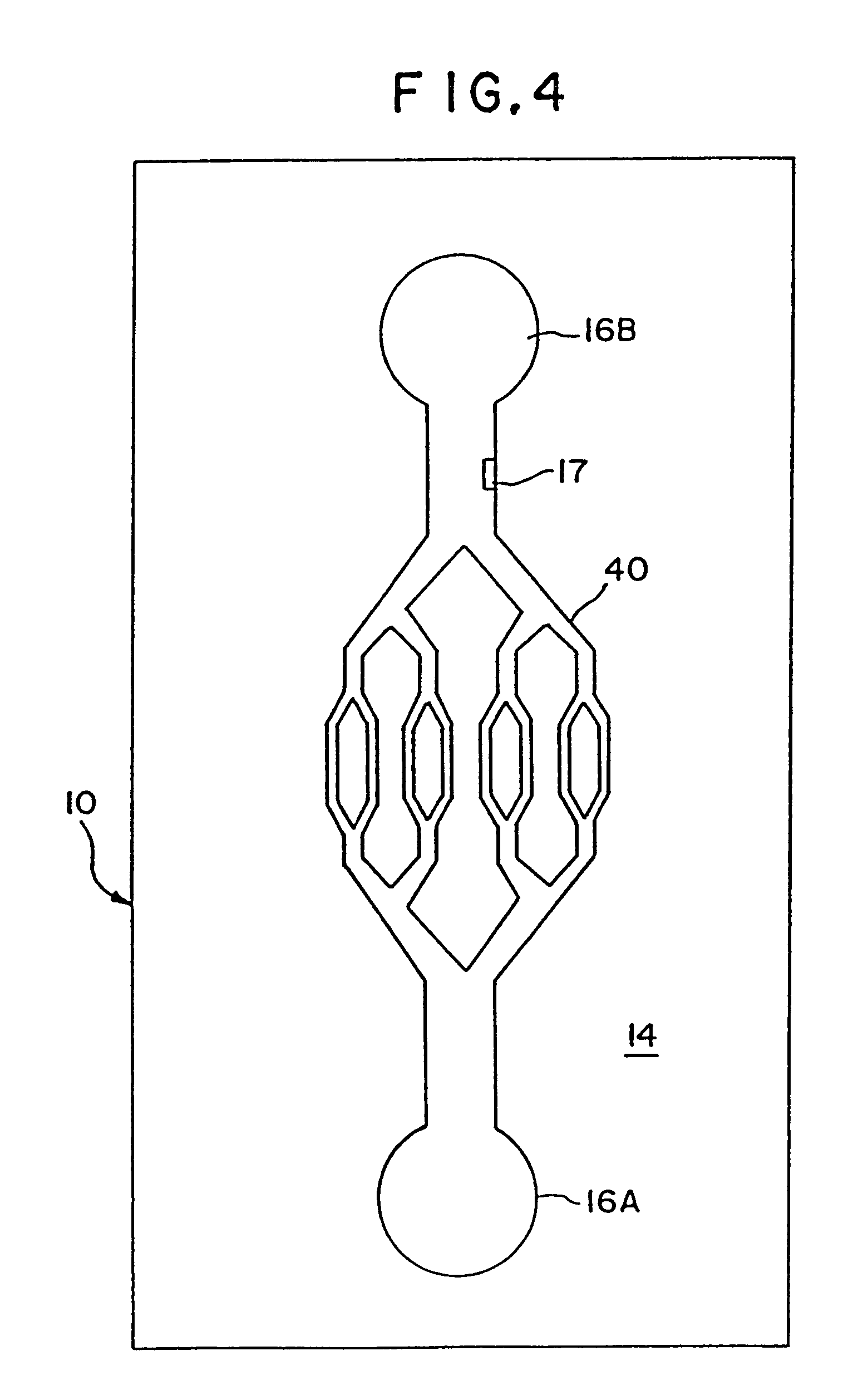
[0013]In the devices, the binding of an analyte to a binding moiety serves as a positive indication of the presence of the analyte in a sample. The mesoscale detection region is provided with a binding moiety capable of specifically binding to the preselected analyte. The binding moiety may be delivered to the detection region in, e.g., a solution. Alternatively, the binding moiety may be immobilized in the detection region. The internal surfaces of the mesoscale detection region of the device may be coated with an immobilized binding moiety to enable the surface to interact with a fluid sample in order to detect or separate specific fluid sample constituents. Antibodies or polynucleotide probes may be immobilized on the surface of the flow channels, enabling the use of the mesoscale flow systems for immunoassays or polynucleotide hybridization assays. The binding moiety also may comprise a ligand or receptor. A binding moiety capable of binding cells via a cell surface molecule may be utilized, to enable the isolation or detection of a cell population in a biological microsample. The mesoscale flow system may also include protrusions or a section of reduced cross sectional area to enable the sorting or lysis of cells in the microsample upon flow through the flow system.
[0017]The mesoscale devices can be adapted to perform a wide range of biological or other tests. A device may include two or more separated flow systems, e.g., fed by a common inlet port, with different binding moieties in, e.g., different detection regions to enable the detection of two or more analytes simultaneously. The device may also comprise a control flow system so that data from the sample region and the control region may be detected and compared. Essentially any test involving detection of the presence or concentration of a molecular or atomic scale analyte, or the presence of a particular cell type, can be implemented to advantage in such structures. The mesoscale devices may provide a rapid chemical test for the detection of pathogenic bacteria or viruses. The devices may also provide a rapid test for the presence or concentration of blood constituents such as hormones. Other applications include but are not limited to a range of other biological assays such as blood type testing.
[0018]The devices as disclosed herein are all characterized by a mesoscale detection region containing a binding moiety that reacts with the analyte component, such as a molecular analyte or a cell type, to detect the presence or concentration of the analyte. The device may be readily sterilized prior to an assay. Assays may be completed rapidly, and at the conclusion of the assay the chip can be discarded, which advantageously prevents contamination between samples, entombs potentially hazardous material, produces only microvolumes of waste fluid for disposal, and provides an inexpensive, microsample analysis. Some of the features and benefits of the devices are summarized in Table 1.

Problems solved by technology

The potential capability of mesoscale structures has not been exploited fully in the life sciences.
Hung and Weissman reported a study of fluid dynamics in micromachined channels, but did not produce data associated with an analytic device.
The art has not fully explored the potential of using mesoscale devices for the analyses of biological fluids and detection of microorganisms.
The inherent delay in such methods frequently necessitates medical intervention prior to definitive identification of the nature of an infection.
In industrial, public health or clinical environments, such delays may have serious consequences.

Method used


Image

  • Device and method for the detection of an analyte utilizing mesoscale flow systems
  • Device and method for the detection of an analyte utilizing mesoscale flow systems
  • Device and method for the detection of an analyte utilizing mesoscale flow systems

Examples


example 1

[0076]Capillary agglutination of red blood cells and immobilized anti-A antiserum was examined in a series of silicon substrates 14 (shown schematically in FIG. 6), fabricated with flow channels 20 of varying width. The silicon substrates 1–5 included flow channels 20A and B with a depth of 10 μm and widths ranging from 20 to 300 μm (Table 2). The inside surface of the channels were coated with anti-A (1:10 dilution) by first filling the channel with the antibody (capillary action) and allowing it to dry. A Type blood (diluted 1:5) was then introduced into channel 20 from inlet port 16 by capillary action and the channel was observed visually using a microscope (Leitz Aristomet). Results are summarized in Table 2.

[0077]

TABLE 2DEPTHCHANNEL WIDTHSUBSTRATE #(μm)(μm)AGGLUTINATION110A:20 +B:40 +210A:60 +B:80 +310A:100+B:120+410A:150+B:200+510A:250+B:300+

example 2

[0078]A plastic-silicon hybrid was fabricated by attaching a plastic (3M transparency sheet) cover over the silicon substrate 14, which is microfabricated with flow channels 20 with entry ports 16 on opposite sides of the channel and a central detection chamber 22 (shown schematically in FIG. 7). A dilution of anti-A (in 0.05 M sodium bicarbonate pH 9.6) and a 1:10 dilution of Type A blood in saline were introduced via syringe using a holder into the entry ports 16 on opposite ends of the channel 20. The solutions mixed together in the central chamber 22 and agglutination was observed through the plastic cover by light microscopy. The results are summarized in Table 3.

[0079]

TABLE 3AGGLUTINATION INANTI-ADILUTIONCHANNELGamma Kit1:20 +Gamma Murine Mono1:20 +Gamma Human Dilution1:5 +Immucor Affinity pure1:100+Immucor Ascites1:100+

example 3

[0080]A plastic-silicon hybrid was fabricated by attaching a piece of plastic (3M transparency sheet) over a silicon substrate 14 etched with a mesoscale flow channel 20 having entry ports 16 microfabricated on opposite sides of the channel and a central mesoscale mixing chamber 22 (shown schematically in FIG. 7). A solution of mouse IgG (50 μg / mL in 0.05 M sodium bicarbonate pH 9.6) (SIGMA Cat. no. 1–5381) and a 1:20 dilution of goat anti-mouse IgG (H&L)—fluorescence carboxylate beads (Polysciences, Inc.) in PBS buffer were introduced via syringe using a holder into the entry ports on opposite ends of the channel. The solutions mixed together in the central chamber 22 and agglutination was observed through the transparent plastic cover by light microscopy.


PUM

PropertyMeasurementUnit
total volumeaaaaaaaaaa
volumeaaaaaaaaaa
depthaaaaaaaaaa

Abstract

Disclosed are devices for detecting the presence of a preselected analyte in a fluid sample. The devices comprise a substrate microfabricated to define a sample inlet port, and a mesoscale flow system that includes a sample flow channel extending from the inlet port. The mesoscale flow system further includes an analyte detection region in fluid communication with the flow channel comprised of a binding moiety for specifically binding the analyte. The detection region is constructed with a mesoscale dimension sufficiently small to enhance binding of the binding moiety and the analyte. The binding moiety may be immobilized in the detection region. The mesoscale detection systems of the invention may be used in a wide range of applications, including the detection of cells or macromolecules, or for monitoring reactions or cell culture growth.

Description

REFERENCE TO RELATED APPLICATIONS[0001]This is a continuation of U.S. patent application Ser. No. 10 / 348,438, filed Jan. 21, 2003, which is a continuation of U.S. patent application Ser. No. 09 / 237,523, filed Jan. 27, 1999, now U.S. Pat. No. 6,551,841, which is a continuation of U.S. patent application Ser. No. 08 / 811,873, filed Mar. 5, 1997, now U.S. Pat. No. 5,866,345, which is a continuation of U.S. patent application Ser. No. 08 / 347,498, filed Nov. 30, 1994, now U.S. Pat. No. 5,637,469, which is a continuation of U.S. patent application Ser. No. 07 / 877,702, filed May 1, 1992, now abandoned. The entire disclosure of each of the aforementioned applications is incorporated by reference in the present application.BACKGROUND OF THE INVENTION[0002]This invention relates generally to methods and apparatus for conducting analyses. More particularly, the invention relates to the design and construction of small, typically single-use, modules capable of receiving and rapidly conducting a ...

Claims


Application Information

Patent Timeline
Patent Type & Authority Patents(United States)
IPC IPC(8): C12M3/00B01F5/06B01J19/00B01L3/00B01L7/00B01L9/00C12M1/26C12M1/34C12M3/08C12Q1/68C40B40/06
CPCB01J19/0093B01L3/5027B01L3/502707B01L3/502715B01L7/52B01L7/525B01L9/527C12Q1/686B01F15/0264B01F5/0601Y10S436/806B01J2219/0059B01J2219/00722B01L3/50273B01L3/502746B01L3/502761B01L2200/027B01L2200/0647B01L2200/0689B01L2200/10B01L2200/146B01L2300/0627B01L2300/0636B01L2300/0645B01L2300/0681B01L2300/0816B01L2300/0822B01L2300/0861B01L2300/0864B01L2300/0867B01L2300/087B01L2300/0883B01L2300/0887B01L2300/1827B01L2300/1861B01L2400/0406B01L2400/043B01L2400/0487B01L2400/086C12Q2565/629C40B40/06Y10S436/805Y10S977/923Y10S977/953Y10S435/81Y10S436/807Y10S366/03Y10S435/97Y10S436/809B01F25/41B01F35/7182
Inventor WILDING, PETERKRICKA, LARRY J.ZEMEL, JAY N.
Owner THE TRUSTEES OF THE UNIV OF PENNSYLVANIA
Learn More