
Source-independent full waveform inversion of seismic data

Inactive Publication Date: 2006-02-14
RGT UNIV OF CALIFORNIA
View PDF0 Cites 93 Cited by
  • Summary
  • Abstract
  • Description
  • Claims
  • Application Information

AI Technical Summary

Benefits of technology

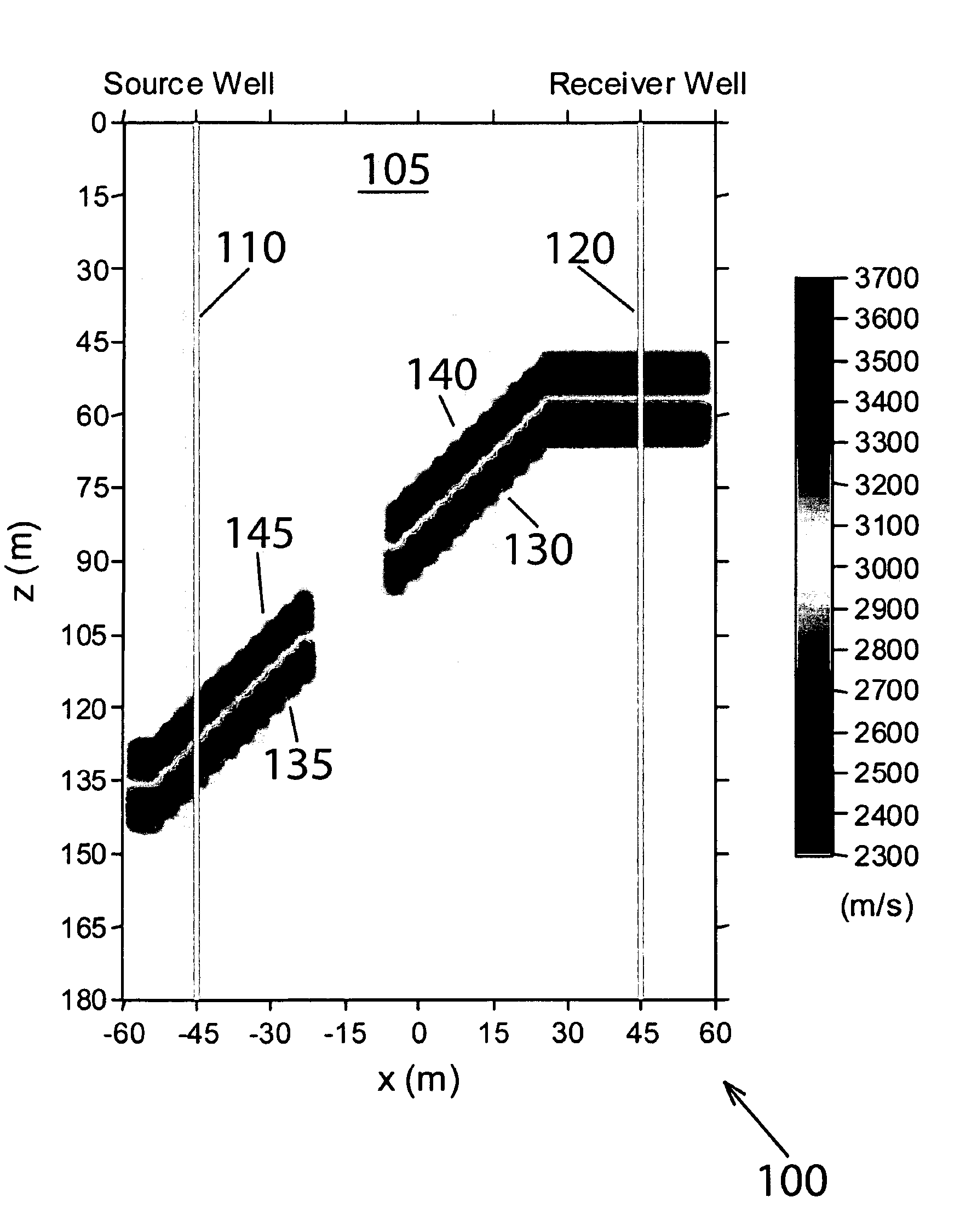
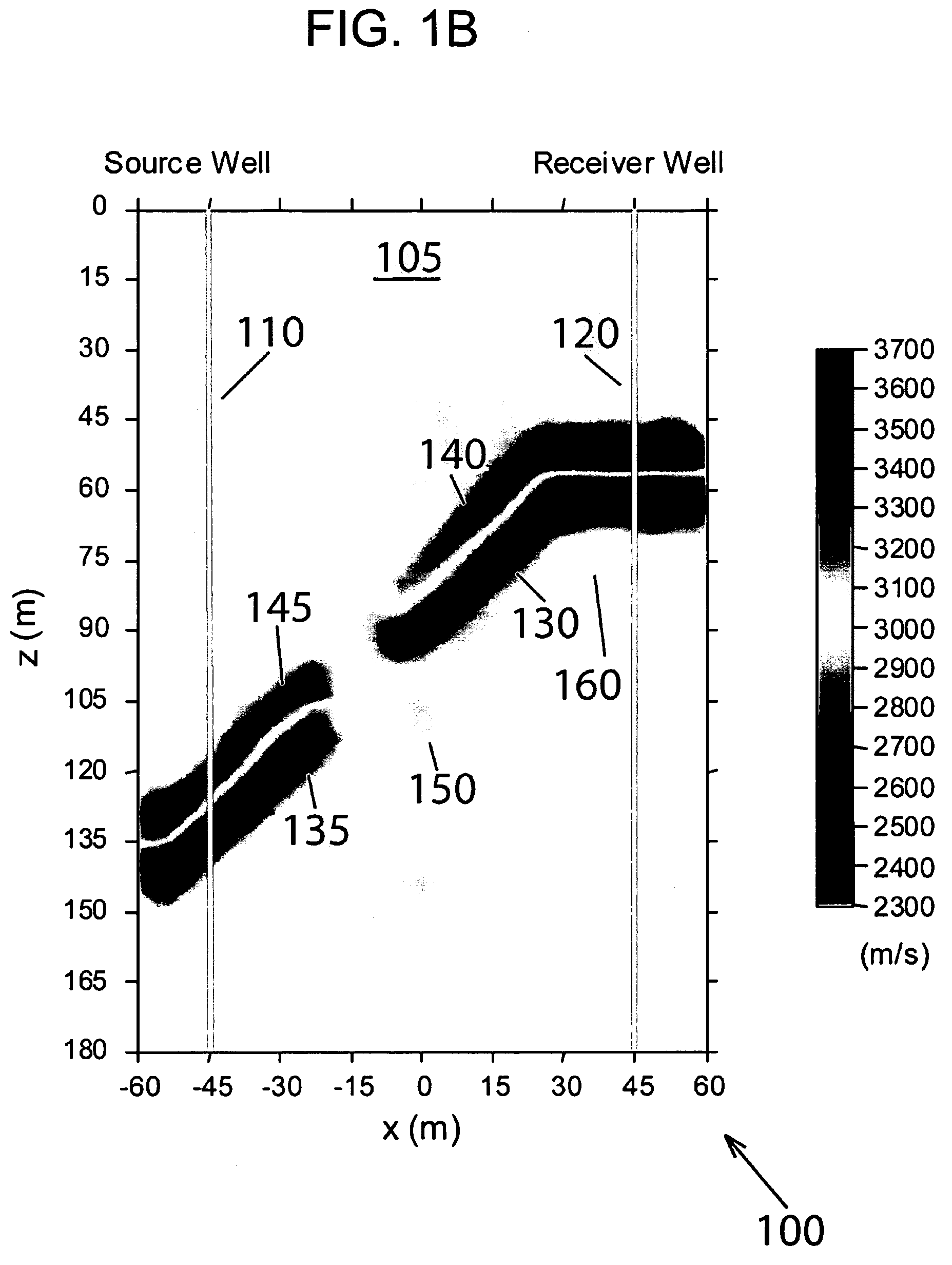
[0010]This invention provides for an iterative method of using normalized waveform inversion to obtain a model parameter describing one or more physical properties of a medium, the method comprising the steps of: a) inputting one or more each of NS source and NG measurement spatial locations; b) measuring time domain data at each of the NG measurement locations resulting from an input waveform at one of the NS source locations propagating through a medium, i) for each of the NS source locations, ii) thereby forming a time domain measurement data set Djid(t), (j=1˜NG; i=1˜NS), where d denotes a data tensor; c) Fourier transforming the time domain measurement data set Djid(t) to create a measurement spectral data set Djid(ω) having frequency and amplitude information for each of the NG measurement locations; d) normalizing the measurement spectral data set Djid(ω) to create a normalized data wavefield Tjid(ω); e) modeling the medium using an iterated model parameter m describing one or more physical properties of the medium, the NS source and the NG measurement spatial locations used as respective model input and model response spatial locations contained within the model of the medium, and initializing the iterated model parameter m with corresponding one or more known bulk properties of the medium being modeled, said modeling step comprising: i) creating a measurement model by: (1) applying a delta function source collocated with the ith NS source, (2) modeling the response at the NG measurement locations, using a time domain modeling method, to create a synthetic medium response at the jth receiver due to the ith source, Pjim(t), m denoting the model response, (3) repeating the applying and modeling steps at each of the NS source locations and NG measurement locations until the measurement model is full, and ii) Fourier transforming the model response Pjim(t), to obtain a frequency domain synthetic response Pjim(ω); iii) forming a normalized modeled wavefield using the frequency domain synthetic response Tjim(ω)=Pjim(ω)[P1im(ω)]−1; and f) minimizing a weighted error, between the normalized data wavefield Tjid(ω) and the normalized modeled wavefield Tjim(ω) of the response of the medium, to a level below an error bound, i) said weighted error met by using the iterated model parameter m, known as the a minimized model parameter m.
[0013]The method of normalized waveform inversion uses minimization of weighted error φ(m) that is calculated by a square of the weighing matrix Wd multiplied by the difference between the normalized data wavefield Tjid(ω) and the normalized modeled wavefield Tjim(ω), or φ(m)=∥Wd(Tjim(ω)−Tjid(ω))∥2 summed over all frequencies, NS sources, and NG receivers. The weighing matrix Wd is an inverse of the standard deviation of the normalized data wavefield Tjid(ω), or other appropriate weighting method indicative of the convergence of the minimization.

Problems solved by technology

The usefulness of the result obtained from the ray tomography may be limited if the objective is to better understand the petrophysical and hydrological ‘properties’ of the soil and rock: an increasingly important subject in characterizing petroleum and geothermal reservoirs, with potential environmental applications.
Full waveform inversion has a major impediment to easy implementation.
The source / medium coupling problem can be resolved to some extent by using a good velocity approximation in geophysical applications; however, the measured signal cannot generally be accurately calibrated, rendering full waveform inversion a technical challenge.

Method used


Image

  • Source-independent full waveform inversion of seismic data
  • Source-independent full waveform inversion of seismic data
  • Source-independent full waveform inversion of seismic data

Examples


Embodiment Construction

Defined Terms

[0023]Computer means any device capable of performing the steps developed in this invention to result in an optimal waterflood injection, including but not limited to: a microprocessor, a digital state machine, a field programmable gate array (FGPA), a digital signal processor, a collocated integrated memory system with microprocessor and analog or digital output device, a distributed memory system with microprocessor and analog or digital output device connected with digital or analog signal protocols.

[0024]Computer readable media means any source of organized information that may be processed by a computer to perform the steps developed in this invention to result in an optimal waterflood injection, including but not limited to: a magnetically readable storage system; optically readable storage media such as punch cards or printed matter readable by direct methods or methods of optical character recognition; other optical storage media such as a compact disc (CD), a d...


PUM


Abstract

A set of seismic trace data is collected in an input data set that is first Fourier transformed in its entirety into the frequency domain. A normalized wavefield is obtained for each trace of the input data set in the frequency domain. Normalization is done with respect to the frequency response of a reference trace selected from the set of seismic trace data. The normalized wavefield is source independent, complex, and dimensionless. The normalized wavefield is shown to be uniquely defined as the normalized impulse response, provided that a certain condition is met for the source. This property allows construction of the inversion algorithm disclosed herein, without any source or source coupling information. The algorithm minimizes the error between data normalized wavefield and the model normalized wavefield. The methodology is applicable to any 3-D seismic problem, and damping may be easily included in the process.

Description

CROSS REFERENCE TO RELATED APPLICATIONS[0001]This application claims priority to U.S. Provisional Patent Application No. 60 / 456,168, filed Mar. 18, 2003 entitled “Method and article of manufacture for source-independent full waveform inversion of seismic data”, which is hereby incorporated by reference in its entirety.STATEMENT REGARDING FEDERAL FUNDING[0002]This invention was made with U.S. Government support under Contract Number DE-AC03-76SF00098 between the U.S. Department of Energy and The Regents of the University of California for the management and operation of the Lawrence Berkeley National Laboratory. The U.S. Government has certain rights in this invention.REFERENCE TO A COMPUTER PROGRAM[0003]Not applicable.BACKGROUND OF THE INVENTION[0004]1. Field of the Invention[0005]The present invention pertains generally to methods used in the inversion of data, more particularly to the inversion of seismic data, and still more particularly to the full wave seismic inversion of seis...

Claims


Application Information

Patent Timeline
IPC IPC(8): G01V1/28G01V1/30
CPCG01V1/30
Inventor LEE, KI HA
Owner RGT UNIV OF CALIFORNIA
Learn More