Image forming apparatus
- Summary
- Abstract
- Description
- Claims
- Application Information
AI Technical Summary
Benefits of technology
Problems solved by technology
Method used
Image
Examples
example 1
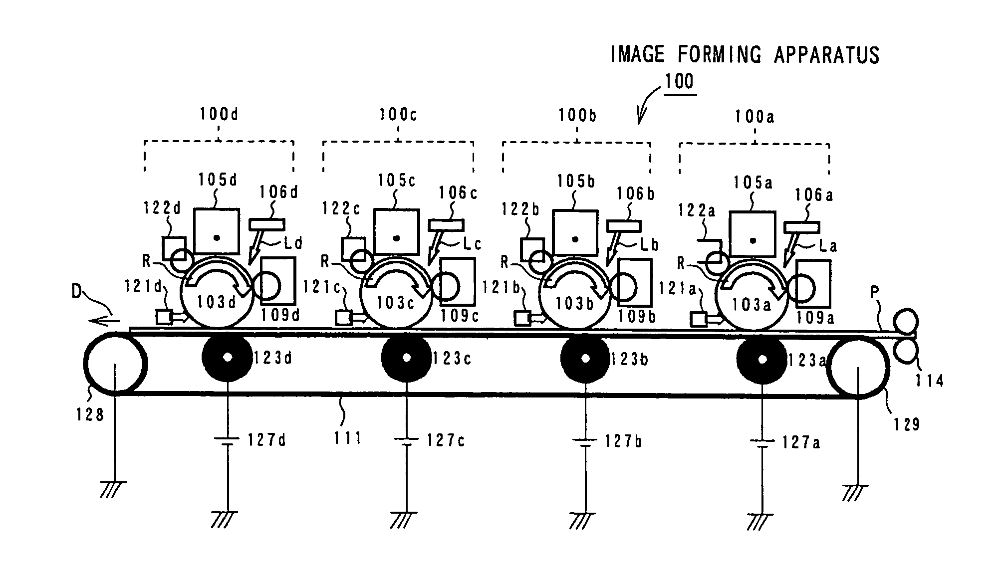
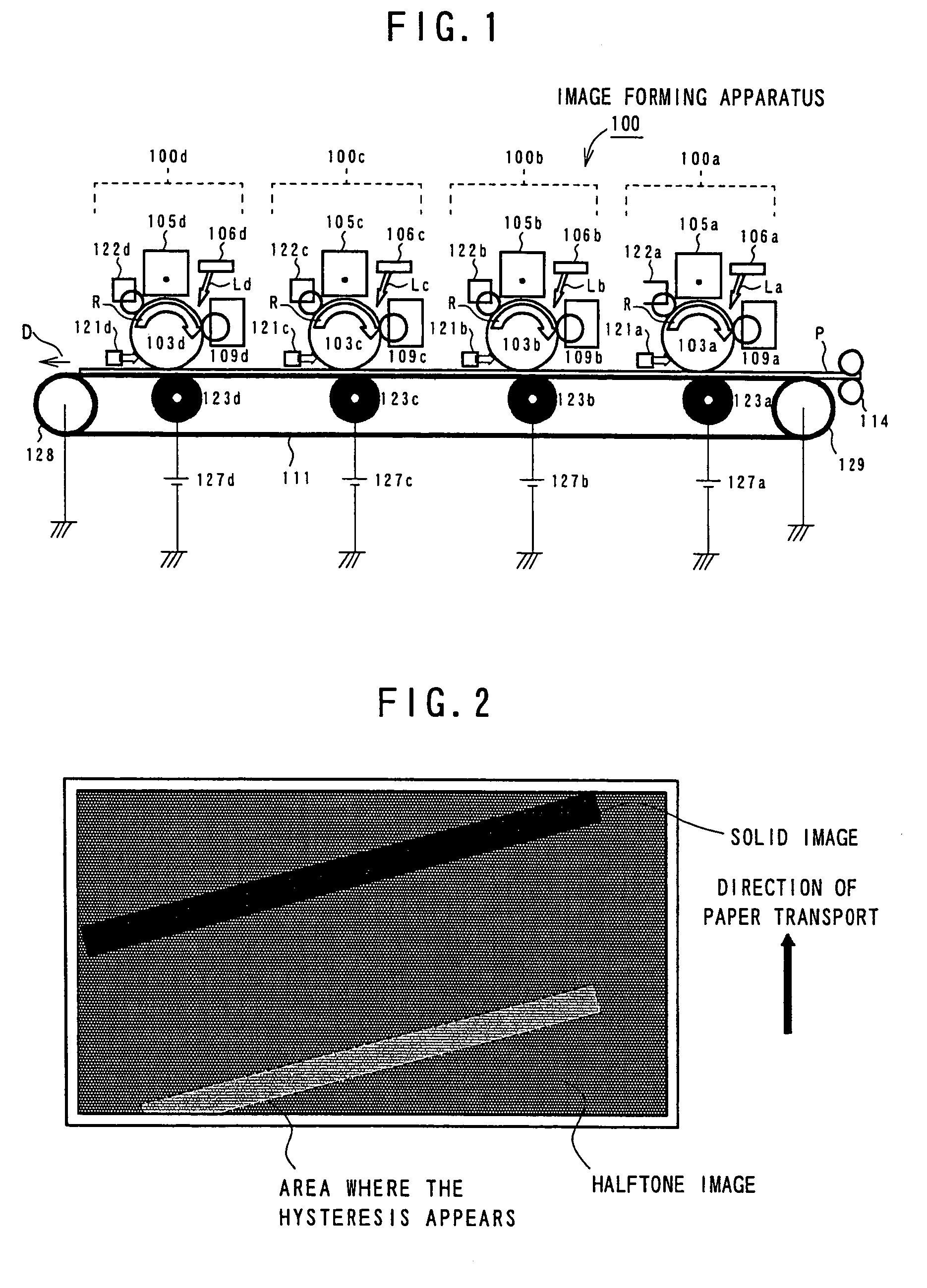
[0039]The image forming apparatus 100 having the above-mentioned configuration is used to form an image as follows. As the first example, an experiment is carried out to compare the conventional image forming method with the image forming method according to the present invention to change the irradiation intensity of a laser in the exposure apparatus with respect to an exposure error. Table 1 shows a result of visually evaluating the hysteresis of output images after developing the yellow, magenta, cyan, and black colors according to the conventional method. In the experiment, the four colors of toners are sequentially supplied to only the image forming unit 100d in order to eliminate an effect of the reverse transfer toner. Accordingly, the evaluation is carried out so that an image of each color can be formed under the same environmental condition. (In Table 1, numeral “4” represents a case most difficult to determine the hysteresis; numeral “1”represents a case easiest to determ...
example 2
[0045]As the second example, an experiment is carried out to compare the conventional image forming method with the image forming method according to the present invention to change the exposure resolution for a specific color. Table 3 shows a result that the untransferred black toner causes the image hysteresis depending on dots per inch. In this case, the method of collecting data follows that for Table 1. An exposure error due to untransferred toner causes the image hysteresis. As described in example 1, the image hysteresis is hardly recognizable on the solid image, but is recognizable on the halftone image containing an area where the development field is inconstant. It will be understood that the image hysteresis can be made inconspicuous by decreasing the exposure resolution for forming an electrostatic latent image compared to the other colors of toners especially with respect to an image forming portion greatly causing an exposure error such as the black toner.
[0046]
TABLE 3...
example 3
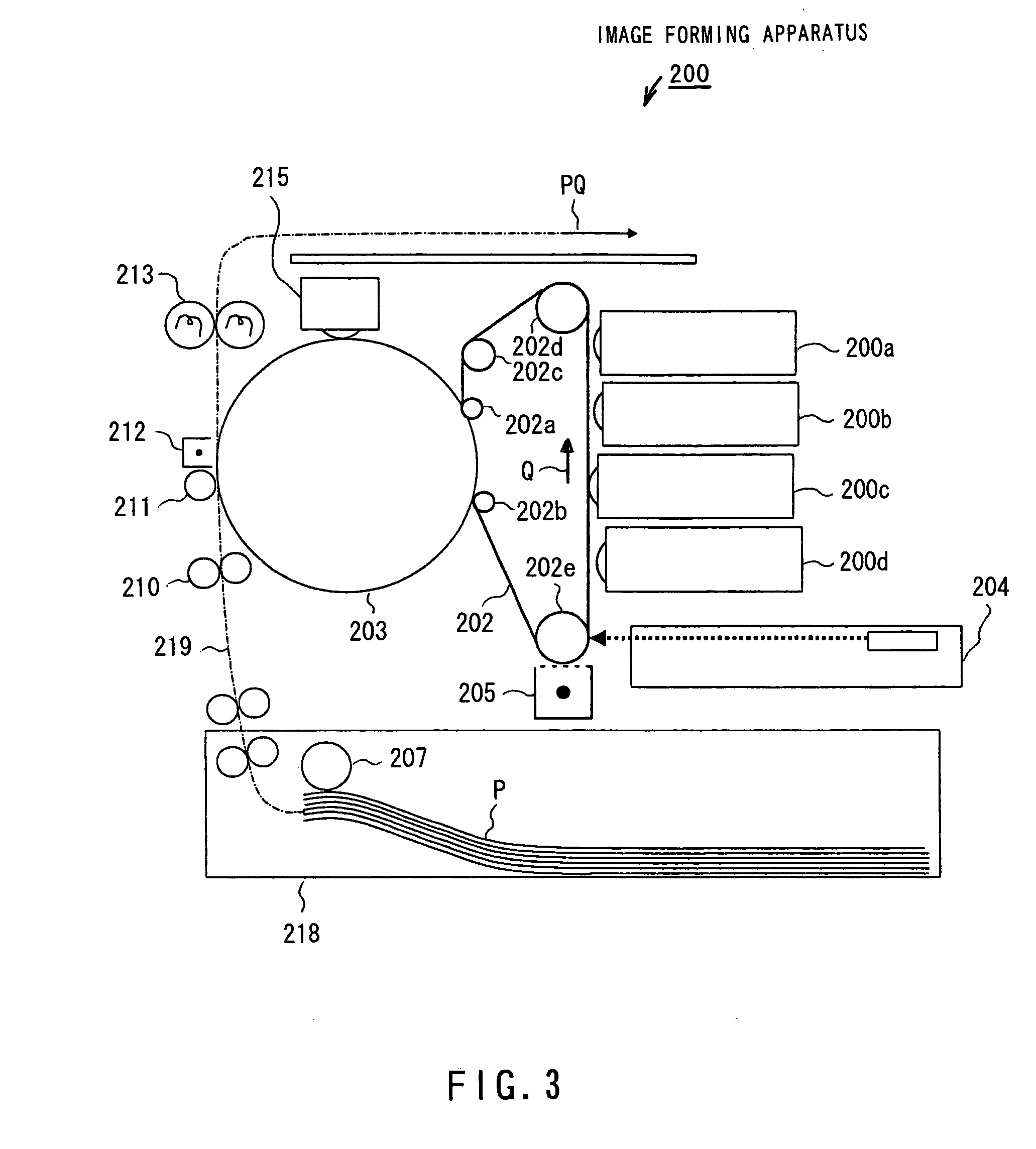
[0049]The following describes another example using an image forming apparatus 200 in FIG. 3 configured on the basis of the 4-rotation image forming system employing the photoreceptor cleanerless system. The configuration of the image forming apparatus 200 in FIG. 3 will be described first. The image forming apparatus 200 in FIG. 3 comprises a photoreceptor belt 202; rollers 202a, 202b, 202c, 202d, and 202e to hold and drive the photoreceptor belt 202; a charger 205; an exposure apparatus 204; four developing apparatuses 200a, 200b, 200c, and 200d; an intermediate transferrer 203; a paper cassette 218 with a sheet feed roller 207; a paper transport apparatus 219; an aligning roller 210; a transfer roller 211; a paper release apparatus 212; a fixing apparatus 213; and a intermediate transferrer cleaner 215.
[0050]In the image forming apparatus 200 of FIG. 3, the photoreceptor belt 202 is in close contact with the surface of the intermediate transferrer 203 by means of the rollers 202a...
PUM
 Abstract
Description
Claims
Application Information
 - R&D
- Intellectual Property
- Life Sciences
- Materials
- Tech Scout
- Unparalleled Data Quality
- Higher Quality Content
- 60% Fewer Hallucinations
Browse by: Latest US Patents, China's latest patents, Technical Efficacy Thesaurus, Application Domain, Technology Topic, Popular Technical Reports.
© 2025 PatSnap. All rights reserved.Legal|Privacy policy|Modern Slavery Act Transparency Statement|Sitemap|About US| Contact US: help@patsnap.com


