
Gas turbine engine starter generator that selectively changes the number of rotor poles

a technology of starter generator and gas turbine engine, which is applied in the direction of engine starter, electric generator control, machines/engines, etc., can solve the problems of relative complex and heavy power electronics circuit, voltage and frequency control, and suffer certain drawbacks, so as to reduce cleaning and maintenance, reduce weight and cost, and increase the wear life of dc brushes

Inactive Publication Date: 2006-02-07
HONEYWELL INT INC
View PDF28 Cites 18 Cited by
  • Summary
  • Abstract
  • Description
  • Claims
  • Application Information

AI Technical Summary

Benefits of technology

[0009]The present invention provides a starter-generator that does not incorporate relatively complex power conversion and frequency control circuits, which reduces the weight and cost as compared to some current starter-generators. The starter-generator can increase the wear life of its DC brushes, which reduces cleaning and maintenance, and the starter-generator can provide a relatively smooth startup, which improves performance during startup.

Problems solved by technology

The above-described starter-generator may include relatively complex and heavy power electronics circuits in the control device.
For example, some control devices may include inverters, for converting DC to AC power, rectifiers, for converting AC power to DC power, and potentially complex voltage and frequency control circuits.
Although brush-type DC machines may alleviate the need for some of these complex and heavy electronic circuits, these also suffer certain drawbacks.
For example, the brushes tend to wear fairly quickly, which can reduce machine reliability and increase the need for periodic maintenance and cleaning.
Some brush-type DC machines can also suffer what is known as torque ripple during startup.
In some instances, the torque ripple can be large, which can result in poor starter performance.

Method used


Image

  • Gas turbine engine starter generator that selectively changes the number of rotor poles
  • Gas turbine engine starter generator that selectively changes the number of rotor poles
  • Gas turbine engine starter generator that selectively changes the number of rotor poles

Examples


Embodiment Construction

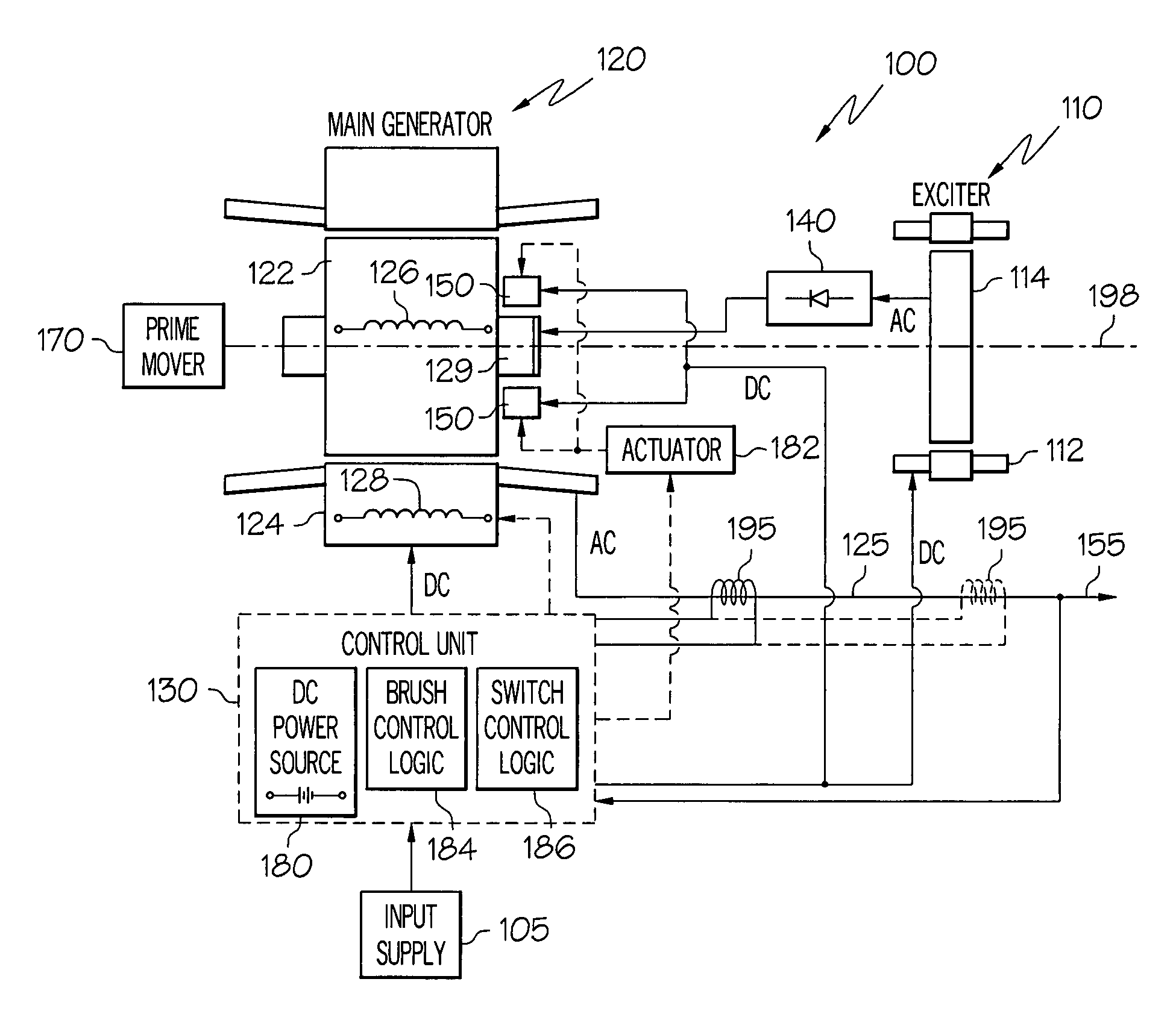
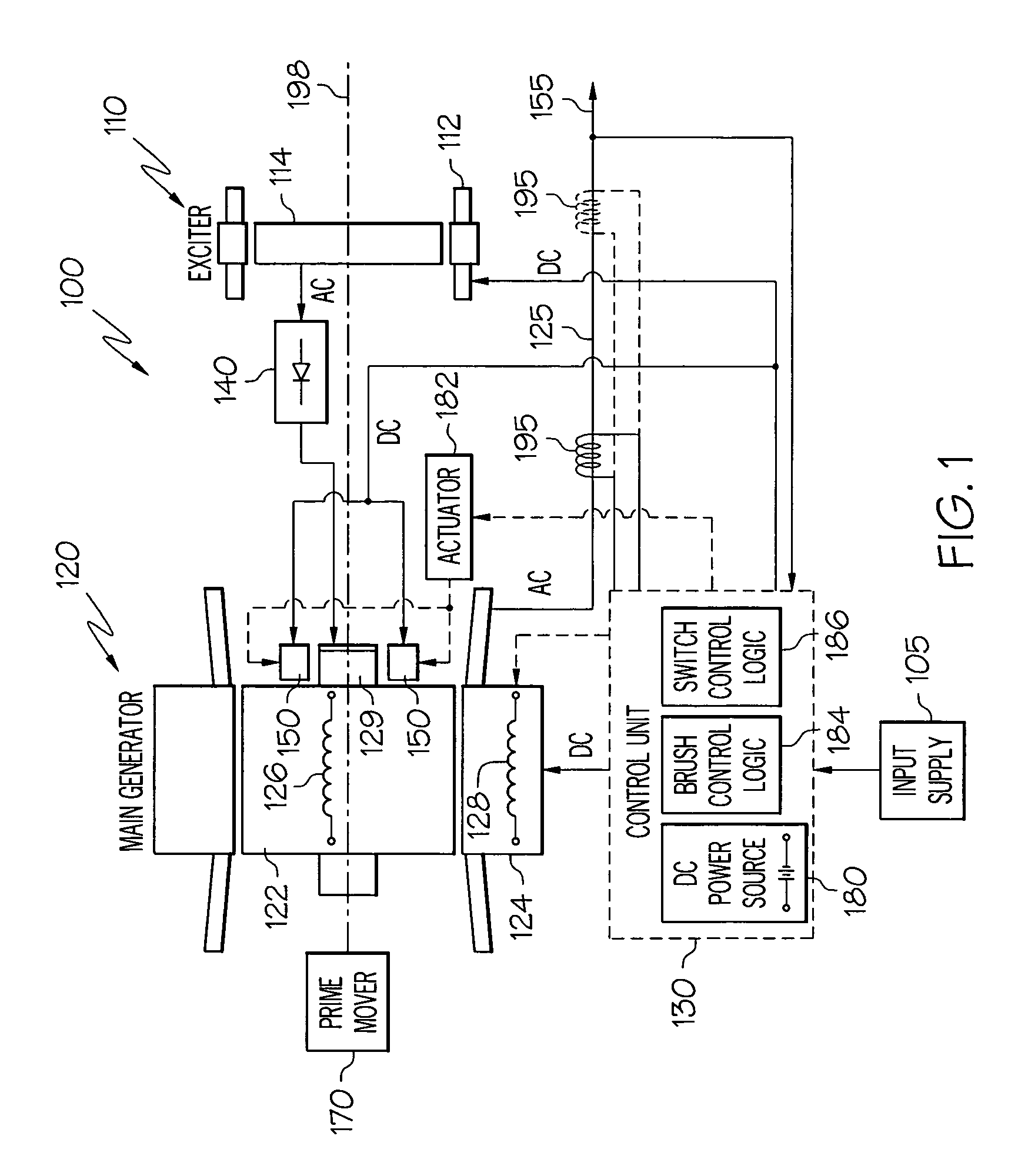
[0020]A functional schematic block diagram of one embodiment of a motor / generator system 100 is shown in FIG. 1. This exemplary motor / generator system 100 includes an exciter 110, a main motor / generator 120, a motor / generator control unit 130, one or more rectifier assemblies 140, and one or more pairs of brushes 150. It is noted that the motor / generator system 100 may be used as a starter-generator for a gas turbine engine in aircraft, space, marine, land, or other vehicle-related applications where gas turbine engines are used. For aircraft applications, gas turbine engines are used for propulsion (e.g., the aircraft's main engines) and / or for power (e.g., the auxiliary power unit (APU)).

[0021]When the motor / generator system 100 is operating in generator mode, a rotor 122 of the main motor / generator 120, as will be described more fully below, is configured as an M-pole rotor, and the brushes 150 are preferably moved out of physical contact with the main motor / generator rotor 122. ...


PUM


Abstract

A rotating electrical machine, such as an aircraft starter-generator, that may be operated in either a motor mode or an generator mode. The machine includes a main rotor that is selectively configurable as an M-pole rotor or an N-pole rotor. The machine can also include DC brushes that are selectively moveable into, and out of, electrical contact the main rotor, to thereby electrically couple and decouple a DC power source to and from, respectively, the rotor windings.

Description

CROSS-REFERENCE TO RELATED APPLICATIONS[0001]This application is a continuation of U.S. application Ser. No. 10 / 391,353, filed Mar. 17, 2003, now abandoned.FIELD OF THE INVENTION[0002]The present invention relates to rotating electrical machines such as starter generators for gas turbine engines and, more particularly, to a starter generator that selectively changes the number of rotor poles between operation as a DC motor and an AC generator.BACKGROUND OF THE INVENTION[0003]An aircraft may include various types of rotating electrical machines such as, for example, generators, motors, and motor / generators. Motor / generators are used as starter-generators in some aircraft, since this type of rotating electrical machine may be operated in both a motor mode and a generator mode. A starter-generator may be used to start the engines or auxiliary power unit (APU) of an aircraft when operating as a motor, and to supply electrical power to the aircraft power distribution system when operatin...

Claims


Application Information

Patent Timeline
Patent Type & Authority Patents(United States)
IPC IPC(8): H02P9/44H02K19/28H02K23/52
CPCH02K23/52H02K19/28
Inventor XU, MINGZHOUCHEN, WEIDUDDECK, MICHAEL W.PEARSON, WAYNE T.SCHERZINGER, WILLIAM M.
Owner HONEYWELL INT INC
Learn More