
Method and system for thick-film deposition of ceramic materials

a technology of ceramic materials and thick films, applied in the direction of solid-state diffusion coating, nuclear engineering, railway components, etc., can solve the problem that the geometries of objects built using this process cannot be achieved by machining or molding processes, and achieve the effect of rapid prototyping and small-scale production

Inactive Publication Date: 2006-02-07
VANDERBILT UNIV
View PDF13 Cites 52 Cited by
  • Summary
  • Abstract
  • Description
  • Claims
  • Application Information

AI Technical Summary

Benefits of technology

The invention is a method and system for fabricating ceramic parts using a laser liquid patterning process. This method can create objects with complex geometries and can also join ceramic parts to other materials like metals. The process allows for rapid prototyping and small-scale production of ceramic objects. The method can also be used to create thermal barrier coatings, precision electronic parts, and biomedical devices like implantable electronics and drug pumps. The process can use metallic or semiconductor particles and can also be used to join ceramic parts to other ceramic parts. The invention also includes a laser liquid patterning apparatus and a powder heating system. The method can create new phases and can also deposit high temperature superconductors. The technical effects of this invention include improved precision and flexibility in ceramic fabrication and the ability to create complex objects with unique properties.

Problems solved by technology

Objects built using this process can have geometries impossible to achieve by machining or molding processes.

Method used


Image

  • Method and system for thick-film deposition of ceramic materials
  • Method and system for thick-film deposition of ceramic materials
  • Method and system for thick-film deposition of ceramic materials

Examples


Embodiment Construction

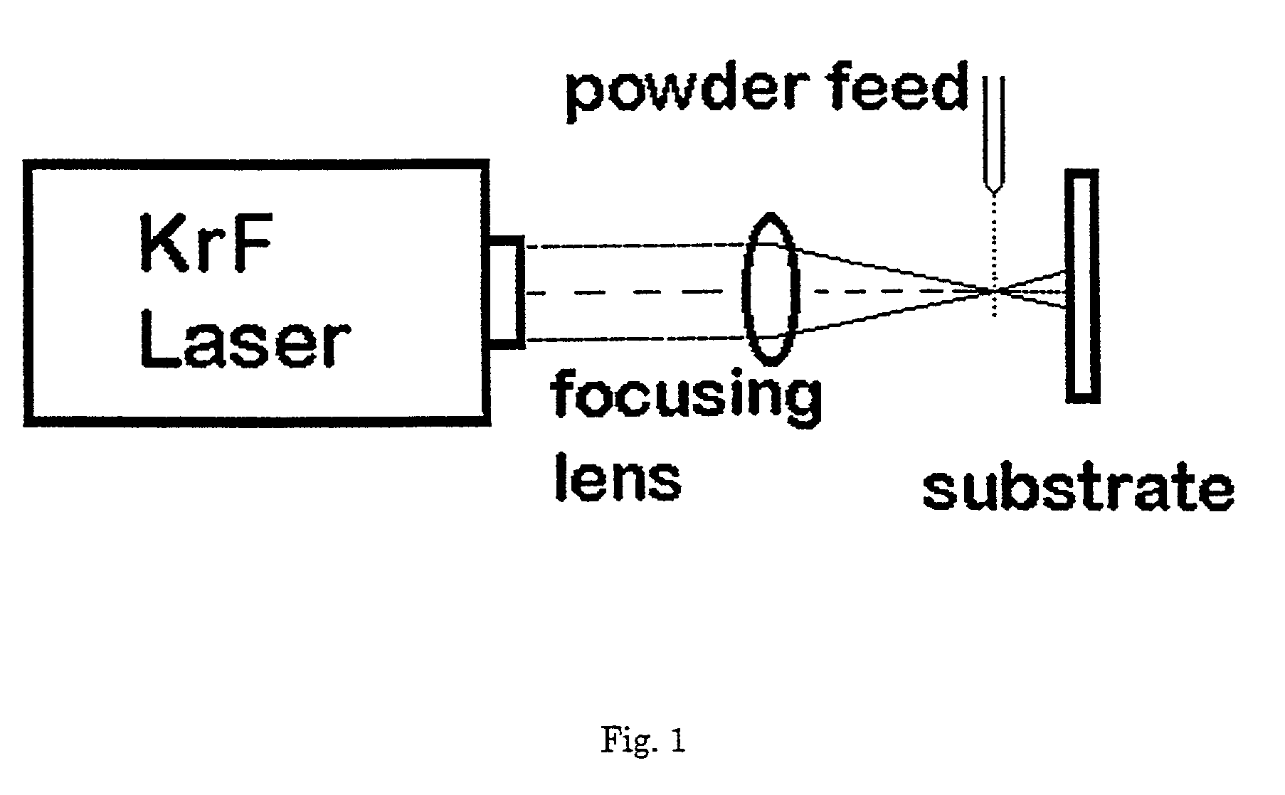
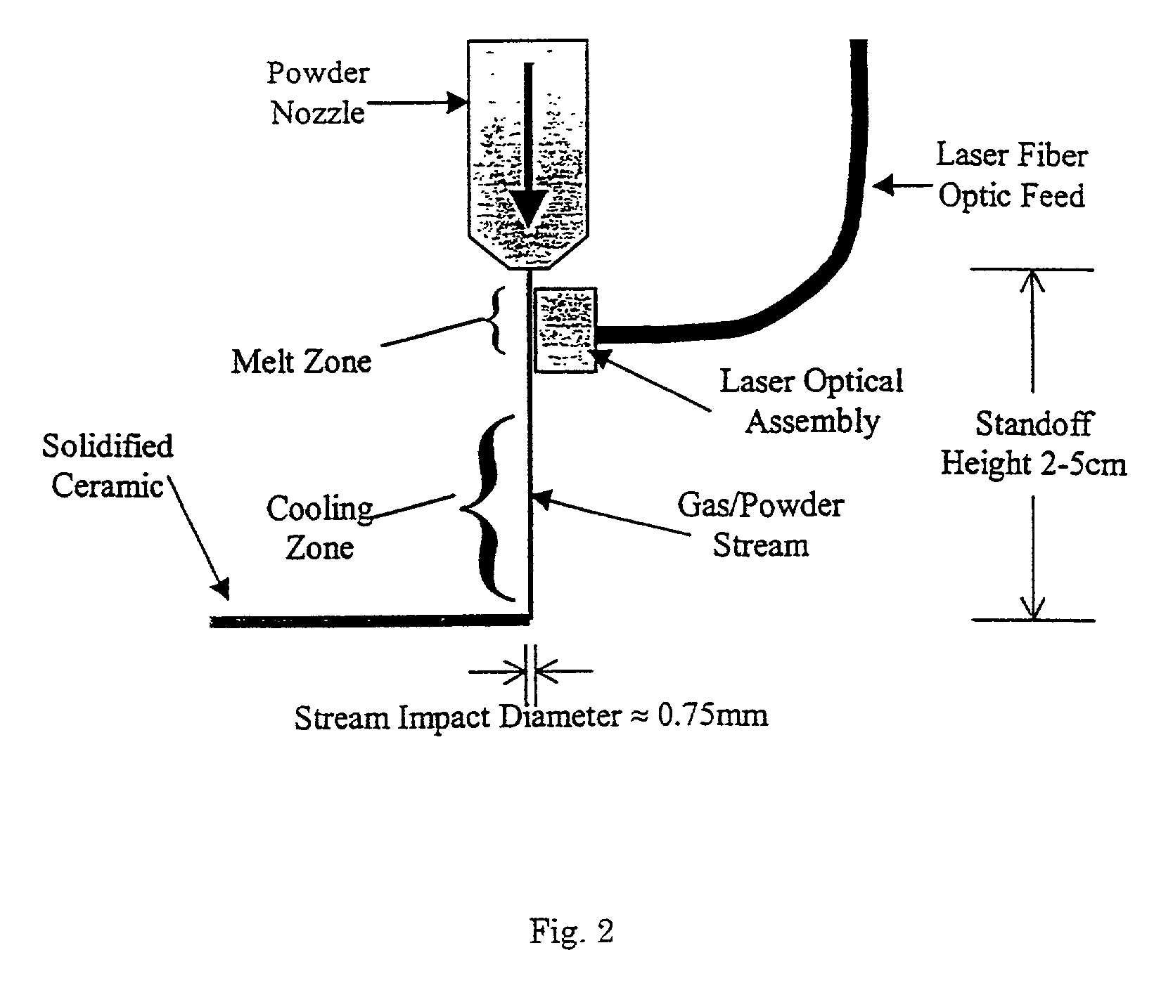
[0029]The method of this invention relies generally on novel process steps that are combined to solve the principal problems with existing techniques. These innovations include a powder nozzle that can focus a gas-entrained powder into a narrow stream with very low divergence. The system and method further include a high flux optical radiation source that can melt ceramic and other particles while in flight thereby decoupling the heat source from the substrate and part, mitigating problems with heat transfer. Another step uses gas cooling to precisely undercool molten ceramic particles while in flight to obtain ceramic phase selection from the melt. For example, in Y123 high temperature oxide superconductors it is possible to bypass two peritectic reactions (involving undesirable Y2O3 and 211 phases) and solidify the 123 crystal structure directly from the undercooled melt. In combination, these innovations allow direction of a thin stream of ceramic material that will rapidly solid...


PUM

PropertyMeasurementUnit
diameteraaaaaaaaaa
temperatureaaaaaaaaaa
velocityaaaaaaaaaa

Abstract

A method of depositing a solid film on a substrate in which a stream comprising particles suspended in a transport gas is moved through a heating zone. The particles are combined with the transport gas from a powder feeder operatively coupled to a gas flow tube. The particle stream is directed toward the heating zone by ejecting the powder stream from a nozzle connected to a distal end of the gas flow tube. A radiation source is directed at the suspended particles as they move through the heating zone so that the particles heated to a molten state. The droplets are undercooled in a cooling zone before impact with the substrate.

Description

[0001]This application claims the benefit of Provisional application Ser. No. 60 / 198,678, filed Apr. 20, 2000.TECHNICAL FIELD[0002]A portion of the disclosure of this patent document contains material that is subject to copyright protection. The copyright owner has no objection to the facsimile reproduction by anyone of the patent document or the patent disclosure, as it appears in the Patent and Trademark office patent file or records, but otherwise reserves all copyright rights whatsoever.[0003]The present invention relates generally to the growth of ceramic films on a substrate using free-form deposition. More particularly, this invention pertains to the formation of ceramic thick-films on a substrate using undercooled ceramic particles.BACKGROUND ART[0004]Rapid prototyping using stereo lithography and plastic materials has enjoyed great commercial success. The natural extension of this process to metallic and ceramic materials has been tried using free form deposition techniques...

Claims


Application Information

Patent Timeline
Patent Type & Authority Patents(United States)
IPC IPC(8): C23C14/30C23C14/28C23C8/00C04B35/45C23C4/12C23C24/04
CPCC04B35/4508C04B35/62665C23C24/04C23C4/12C23C4/121C04B2235/3215C04B2235/3224C04B2235/3281C04B2235/3282C04B2235/3225C23C4/123C23C14/30
Inventor HOFMEISTER, WILLIAM
Owner VANDERBILT UNIV
Learn More