High throughput capacity spinner for manufacturing dual-component curly fibers

a technology of curly fibers and spinners, which is applied in auxillary shaping apparatus, lighting and heating apparatus, furnace types, etc., can solve the problems of ineffective rotary fiber forming process, unsuitable thick and long fibres for insulating products, and inability to effectively compete with non-rotary fiber forming processes. achieve better thickness recovery, improve volume filling ability, and improve compression ratio

Inactive Publication Date: 2006-01-31
OTTAWA FIBER
View PDF42 Cites 4 Cited by
  • Summary
  • Abstract
  • Description
  • Claims
  • Application Information

AI Technical Summary

Benefits of technology

[0018]Thermal insulation material made as a mixture of single-glass straight and dual-glass curly fibers is expected to allow for substantially higher compression ratios during the product packaging stage, since a curly fiber component certainly can offer some extra springiness to the product, and this results in a better thickness recovery after compression release. It is likely that less binder will be needed to assure a required level of product integrity. Curly fibre has a better volume filling ability than a so called straight one, and naturally allows for some degree of fibre interlocking, mutual entanglement and self-cohesion. Slightly reduced thermal conductivity and therefore potential for some density reduction, is possible. Skin irritation and product dustiness, which are factors particularly important to product end-users or installers, should in principle be less pronounced as well.
[0019]The object of the present invention is to provide a dual-glass spinner for manufacturing bi-component curly glass fibers at a production rate in principle comparable with the single-glass spinner operation. A mixed dual-glass / single-glass fibre insulation product can be made with a substantially improved allowable compression ratio, as determined by the minimum required thickness recovery after unpacking, much reduced binder content, and somewhat improved thermal insulation value.

Problems solved by technology

However, this thick and long fibre is unsuitable for insulating products.
Some other patents disclosing methods of making curly or kinky glass fibers are disclosed in U.S. Pat. Nos. 3,236,616 and 4,145,199, but still these methods are not that practical for making insulation product.
It is generally accepted that a non-rotary fiber forming process can not effectively compete with the rotary one for the economic manufacture of a typical glass fibre insulating product, because of a substantially lower throughput capacity and too coarse fibre to make a good glass wool.
As a consequence, some methods of imparting kink by pulling fibre from a textile bushing and mechanically crimping it by passing fibre, while still in a hot state, through a series of opposed intermeshing gears are not a viable option.

Method used


Image

  • High throughput capacity spinner for manufacturing dual-component curly fibers
  • High throughput capacity spinner for manufacturing dual-component curly fibers
  • High throughput capacity spinner for manufacturing dual-component curly fibers

Examples


Embodiment Construction

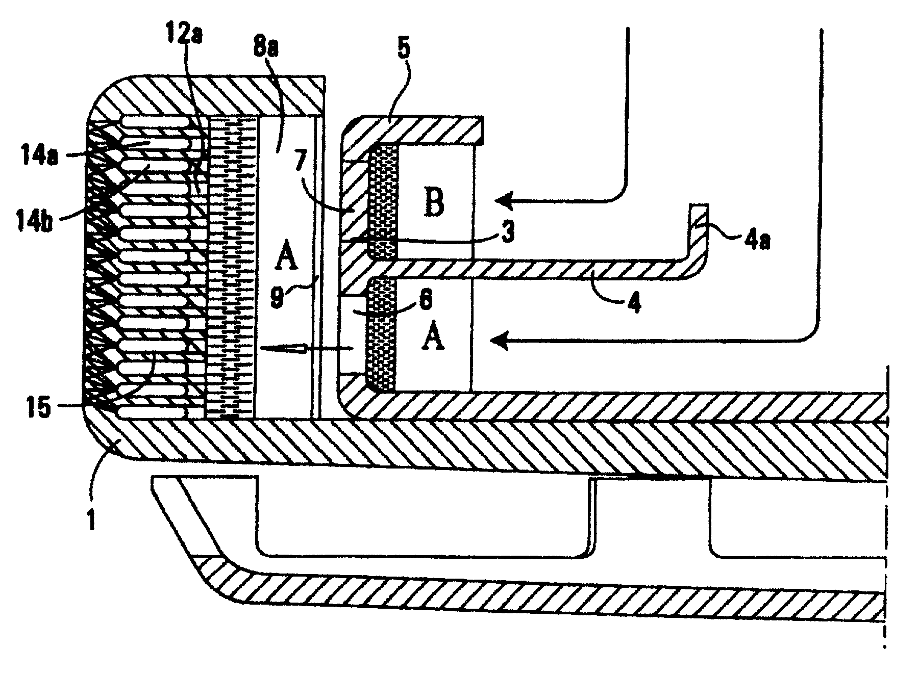
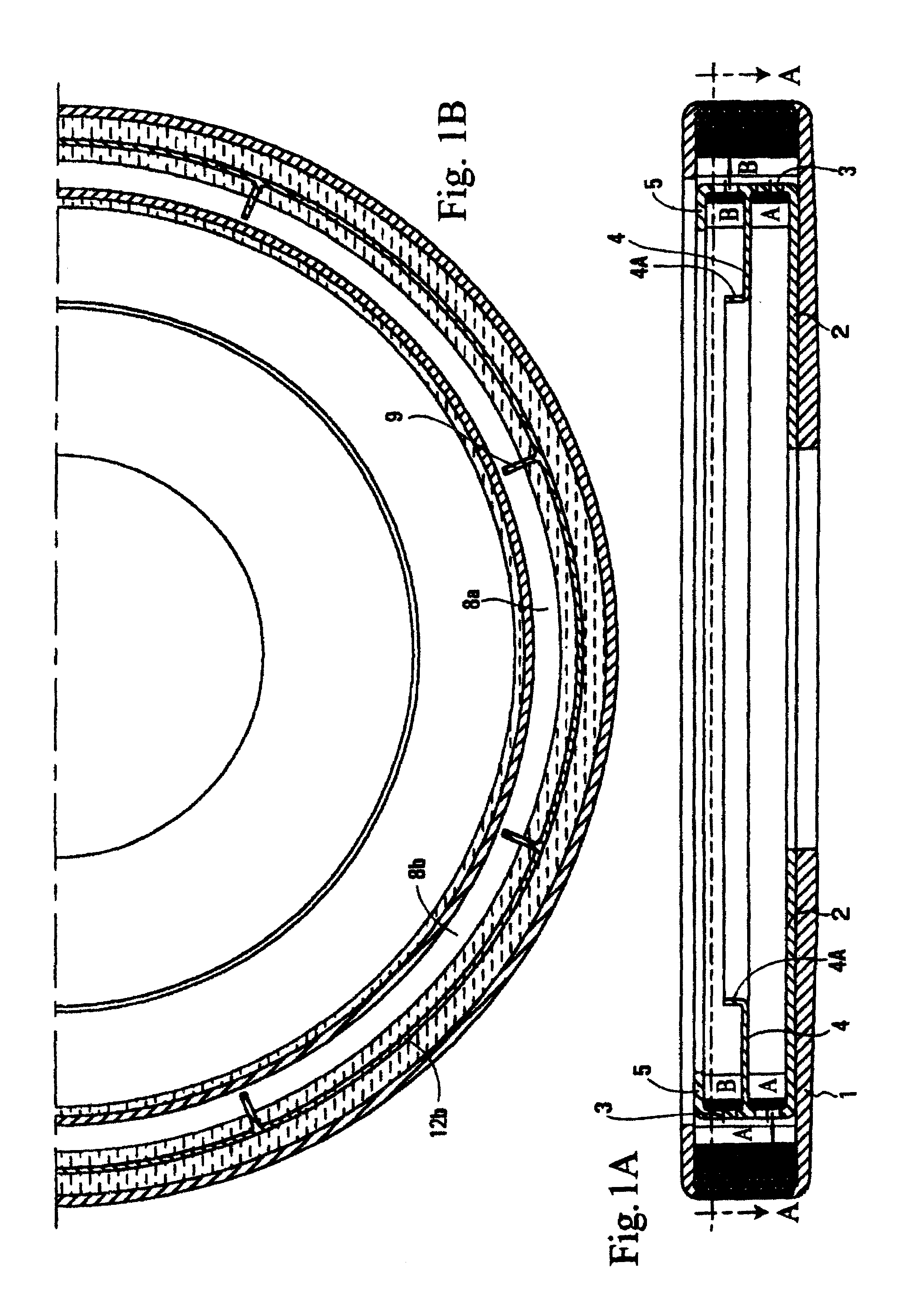
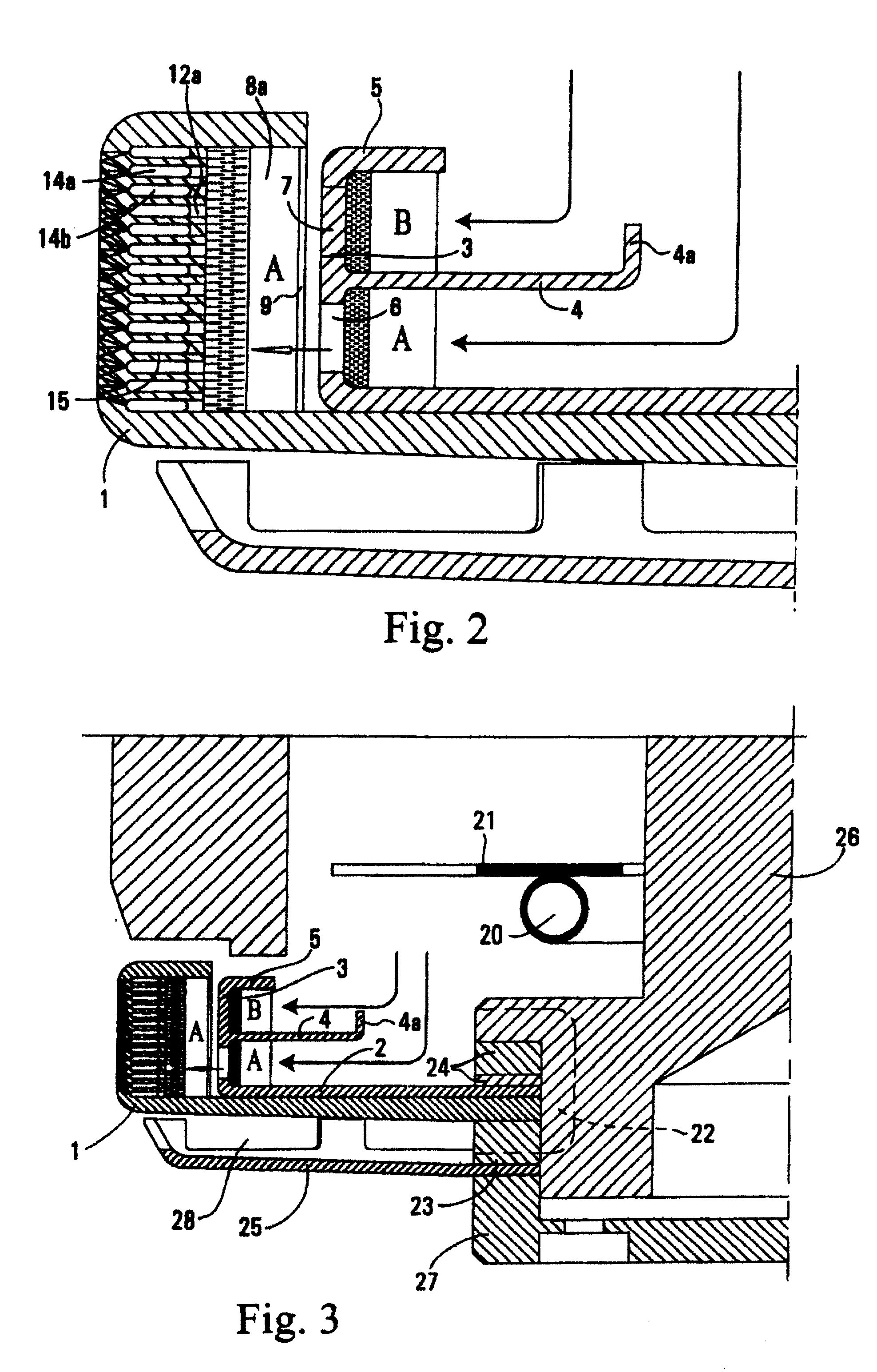
[0031]FIG. 1A is a transverse cross section of a spinner used to produce glass fibers through centrifugal force, heat, and air pressure. The spinner 1 is basically a round dish having a peripheral circumference with holes drilled therein. The spinner has an upper top side flange but otherwise has an open top which permits molten glass to enter into the spinner and be forced to the circumference. In FIG. 1A there is mounted within the spinner a slinger cup 2. The slinger cup is fixedly mounted within the spinner. It has a peripheral wall or rim 3, a slinger cup middle flange 4, and a middle flange upturned member 4A. The slinger cup also has a top flange 5. The purpose of the slinger cup is to separate two molten glasses A and B. Molten glass B is directed into the slinger cup on top of the middle flange 4 whereas molten glass A falls inside the spinner 1 inwardly of the slinger cup middle flange upturned member 4A.

[0032]On examination of FIGS. 1A and 2, one views that a molten strea...


PUM

PropertyMeasurementUnit
angleaaaaaaaaaa
angleaaaaaaaaaa
angleaaaaaaaaaa

Abstract

A spinner and a distributor spinner cup fixedly nested within the spinner are adapted to receive two molten thermoplastic materials of different coefficients of thermal expansion to produce a dual-component glass fiber insulation product. The inside wall of the spinner peripheral side wall is adapted to receive, through horizontal slots adjacently vertically disposed, first and second molten thermoplastic materials and centrifuge same into horizontal annular non-interrupted circumferential cavities disposed above and below one another. Passages lead from exit orifices in each cavity outwardly at differing angles. Passages from first and second thermoplastic material cavities join with one another at orifices on an outer side of the peripheral side wall.

Description

[0001]This application claims priority of Canadian patent application 2,380,215 filed Apr. 4, 2002.[0002]General field of this invention is a method and apparatus for manufacturing dual-component fibers from thermoplastic materials, such as glass or some other mineral or polymer materials, by using a rotary fiber forming process. More particularly this invention belongs to a category of devices for centrifuging dual-component curly glass fibers, where the fibre curl is the result of distinct differences in some physical properties or parameters of the two separate glasses. A most common approach is to utilize two unique glass formulations with a significant difference in their coefficients of thermal expansion.[0003]Typical glass fibre thermal or acoustical insulation product is made of rather short, single glass and basically straight glass fibers. Common method of manufacturing these glass wool type fibers is a rotary fiberizing process, where a single molten glass composition is ...

Claims


Application Information

Patent Timeline
Patent Type & Authority Patents(United States)
IPC IPC(8): C03B37/04D01D5/18
CPCD01D5/18C03B37/044Y02P40/57
Inventor SKARZENSKI, JOSEPHCZASTKIEWICZ, WITOLD S.BANASZKIEWICZ, STAN
Owner OTTAWA FIBER
Why Eureka
Try Eureka