
Electrolytic capacitor and method of producing the same

a technology of electrolytic capacitors and capacitor electrodes, which is applied in the direction of electrolytic capacitors, capacitor electrodes, solid-state devices, etc., can solve the problems of long polymerization time, difficult to grow a conductive polymer layer having a uniform and sufficient thickness, and prolonging the operating time of polymerization, etc., to achieve the effect of repairing partial damag

Inactive Publication Date: 2006-01-24
PANASONIC CORP
View PDF22 Cites 17 Cited by
  • Summary
  • Abstract
  • Description
  • Claims
  • Application Information

AI Technical Summary

Benefits of technology

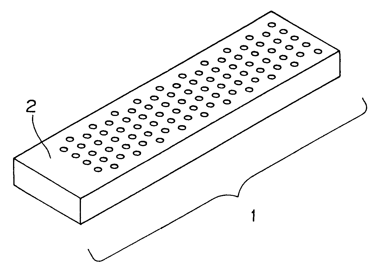
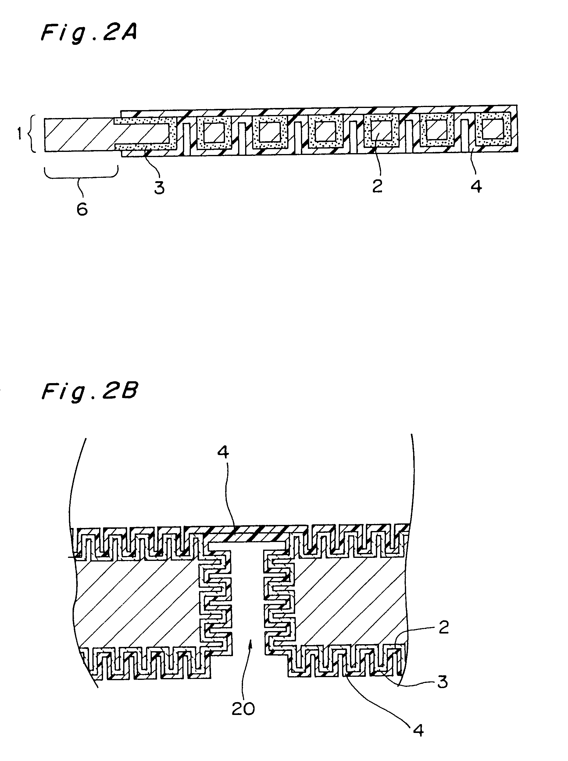
[0034]In the electrolytic polymerization method of the present invention, the conductivity of the cathode-side conductive polymer layer can be raised, the current for electrolysis can be made large, the speed of forming the conductive polymer layer can be increased, and the formation of the conductive polymer layer can be made easier, regardless of whether the start point of electrolytic polymerization is the metal foil, the cathode-side conductive polymer layer or the cathode-side conductive polymer layer provided on the cathode electric collector. Furthermore, in the electrolytic polymerization method according to the present invention, the polymer passes through the through holes in the metal foil and is formed simultaneously in the thickness direction of the anode valve metal foil. Therefore, the polymer can cover the surface of the metal foil immersed in the solution quickly and uniformly, regardless of the size of the valve metal foil. As a result, the conductive polymer layer can be formed quickly and easily as described above. It is therefore possible to obtain an electrolytic capacitor capable of delivering a large capacitance sufficiently close to its design capacitance.
[0035]The method of the present invention, prior to the polymerizing step, comprises a further step of forming a conductive layer which is preformed as part of a cathode layer in contact to a part of or all the surface area of the dielectric layer. In polymerizing, so preformed a conductive layer makes contact to the growing polymer layer and becomes anodic starting points for polymerizing the monomer. Thus, it can promote the polymerizing rate in the growing direction of electrolytic polymerization to extend a area of the polymer on the dielectric layer of the valve metal foil and also to increase a thickness of the polymer.
[0037]The presence of this conductive layer facilitates the formation of the electrolytically-formed conductive polymer layer by electrolytic polymerization. The dielectric layer can thus be covered completely with the formed electrolytically-formed conductive polymer layer.
[0040]Furthermore, The wound electrolytic capacitor can have a sufficiently large capacitance, since the capacitor unit is relatively smaller in size with respect to high capacitance. Moreover, by simply changing or adjusting the length of the electrolytic capacitor unit to be wound, the capacitance can be freely adjusted.
[0042]According to the re-anodizing process, it is possible to repair partial damage at the dielectric layers, owing to mechanical stresses generated in laminating the capacitor units and integrating the metal surface portions.
[0043]In the method of producing the wound electrolytic capacitor anodizing a part of the anode valve metal foil again, after winding an electrolytic capacitor unit in the shape of coil. It is thus possible to repair partial damage at the dielectric layer, owing to mechanical stresses generated at the step of winding the electrolytic capacitor unit.

Problems solved by technology

However, the formation of the conductive polymer layer by the conventional techniques caused some problems.
It was difficult to grow a conductive polymer layer having a uniform and sufficient thickness on the entire surface of the dielectric layer of the oxide film.
In this conventional method, when a conductive polymer layer is formed by electrolytic polymerization on both sides of an anode foil having a relatively large area, it takes a long time for polymerization.
This results in extending the operating time for polymerization.
In order to form a necessary and sufficient conductive polymer layer for the final product, the processes for capacitor production have been complicated and taken a long time, then, requiring high production cost.

Method used


Image

  • Electrolytic capacitor and method of producing the same
  • Electrolytic capacitor and method of producing the same
  • Electrolytic capacitor and method of producing the same

Examples


embodiment 1

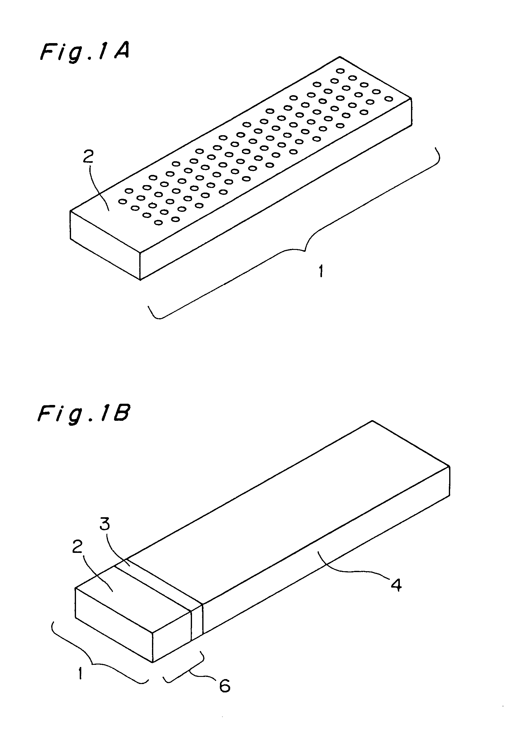
[0074]In the invention, the conductive polymer layer 4 is formed by a method of subjecting the above-mentioned monomer to electrolytically oxidative polymerization. In the method, an electrolyzing electrode is utilized, which is formed previously on one side surface of the anode of the valve metal foil 1.

[0075]This embodiment can use a sheet or foil of metal, such as nickel, as a electrolyzing electrode. Other metals and non-organic substances may also be used if they can act as a positive electrode in the monomer solution for electrolyzing with no corrosion and anodic passivation.

[0076]The electrolyzing electrode and the valve metal, being attached in contact to each other, is immersed into the monomer solution. A current is supplied to the electrolyzing electrode (positive) attached on the valve metal foil and another electrode disposed in the solution so that an electrolytic polymerization reaction starts on the surface of the electrolyzing electrode by anodizing reaction. When t...

embodiment 2

[0097]In the electrolytic capacitor of the present embodiment, a cathode-side conductive polymer layer 5 is formed, as part of a cathode layer, in advance on the dielectric layer 3 on one side surface of the anode valve metal foil 1, as shown in FIG. 5. The electrolytically-formed conductive polymer layer 4, which composes the rest of the cathode layer, a substantial cathode, covers the almost entire surface of the dielectric layer 3, penetrating the through holes 20 to fill their interiors. The cathode-side conductive polymer layer 5 is electrically connected to the electrolytically-formed conductive polymer layer 4, so that both the two conductive polymer layers 4 and 5 are a cathode layer to produce an electrolytic capacitor.

[0098]This electrolytic capacitor is formed by interposing the dielectric layer 3 between the anode valve metal foil 1 and the electrolytically-formed conductive polymer layer 4. This electrolytically-formed conductive polymer layer 4 may be formed uniformly ...

embodiment 3

[0118]In the present embodiment, a conductive polymer layer 5 is formed on a dielectric layer 3 on one side surface of an anode valve metal foil 1 as shown in FIG. 9.

[0119]Furthermore, an electrolytically-formed conductive polymer layer 4 covers the almost entire surface of the dielectric layer 3, and penetrates the through holes 20 in the metal foil 1. A cathode electric collector 13, made of a metal sheet, is electrically connected to the electrolytically-formed conductive polymer layer 4 via the cathode-side conductive polymer layer 5, thereby forming an electrolytic capacitor. This electrolytically-formed conductive polymer layer 4 is formed in a wide area on the dielectric layer 3 and functions as the cathode, whereby the capacitance of the electrolytic capacitor can be raised sufficiently.

[0120]Furthermore, the cathode electric collector 13 electrically connected to the electrolytically-formed conductive polymer layer 4 is formed and used for lead connection.

[0121]Two leads fo...


PUM

PropertyMeasurementUnit
inner diameteraaaaaaaaaa
widthaaaaaaaaaa
thicknessaaaaaaaaaa

Abstract

The present invention provides an electrolytic capacitor having a large capacitance sufficiently close to its design capacitance, and a method of easily producing such an electrolytic capacitor wherein a cathode-side conductive polymer layer of an electrolyzing electrode is formed on at least one side surface of an anode valve metal foil having through holes 20 and a coarsened surface, electrolysis is carried out in a conductive monomer solution, with the polymer layer used as the anode, and an electrolytically-formed conductive polymer layer is formed on the surface of the dielectric oxide film of the valve metal foil, thereby obtaining an electrolytic capacitor, whereby it is possible to easily obtain an electrolytic capacitor having a large capacitance sufficiently close to its design capacitance.

Description

[0001]This is a divisional application of Ser. No. 09 / 317,209, filed May 24, 1999 now U.S. Pat. No. 6,239,965.BACKGROUND OF THE INVENTION[0002]1. Field of the Invention[0003]The present invention relates to an electrolytic capacitor comprising an anode of a valve metal such as aluminum or tantalum, and a cathode of a conductive polymer layer, and also relates to a method of producing such an electrolytic capacitor.[0004]2. Prior Art[0005]A conventional electrolytic capacitor have been composed of an anode formed of the valve metal, a dielectric layer formed of a film of the valve metal oxide, and a cathode formed of a liquid electrolyte or inorganic solid electrolyte, with leads connected to the anode and the cathode, respectively, being packaged to make a product.[0006]The anode is made of aluminum or tantalum as the valve metal, whose oxide metal is used for the dielectric layer. In the case of aluminum electrolytic capacitor, the surface of an aluminum foil is coarsened and anodi...

Claims


Application Information

Patent Timeline
Patent Type & Authority Patents(United States)
IPC IPC(8): H01L51/40H01L21/20H01L21/8242H01G9/02H01G9/025H01G9/04H01G9/048H10B12/00
CPCH01G9/025H01G9/048Y10T29/417
Inventor SHIRAISHI, SEIGOIGAKI, EMIKOTANAHASHI, MASAKAZU
Owner PANASONIC CORP
Learn More