
Heat exchanger

a technology of heat exchanger and heat exchanger plate, which is applied in the direction of manufacturing tools, soldering devices, light and heating equipment, etc., can solve the problems of high production cost and promote tube corrosion, and achieve the effect of improving tube corrosion resistance, promoting tube corrosion, and efficient sealing of tube corrosion resistan

Inactive Publication Date: 2006-01-24
ZEXEL VALEO CLIMATE CONTROL CORP SAITAMA
View PDF10 Cites 48 Cited by
  • Summary
  • Abstract
  • Description
  • Claims
  • Application Information

AI Technical Summary

Benefits of technology

"The present invention is a heat exchanger with improved corrosion resistance of the tubes. This is achieved by using a sacrifice layer on the outer surfaces of the tubes and recessed portions on the outer surfaces of the tubes being filled with brazing material, which melts from the heat exchanger core during the brazing process. The brazing material can be laminated on the heat exchanger core or disposed on the tubes, tanks, and fins. The use of brazing material on the tubes and tanks is costly, so the brazing material is saved by laminating it on the heat exchanger core or on the tubes, tanks, and fins. The brazing material can be supplied from a laminated brazing material on the tanks and / or fins or a paste, stick, or sheet disposed on the tubes, tanks, and fins."

Problems solved by technology

Specifically, the recessed portions on the outer surfaces of the tubes tend to gather dust and water and become a cause of promoting corrosion of the tubes.
When the brazing material for filling the recessed portions is laminated on the plate-shaped material for forming the tubes, the production cost becomes very high.

Method used


Image

  • Heat exchanger
  • Heat exchanger
  • Heat exchanger

Examples


Embodiment Construction

[0030]Embodiments of the present invention will be described in detail with reference to the accompanying drawings.

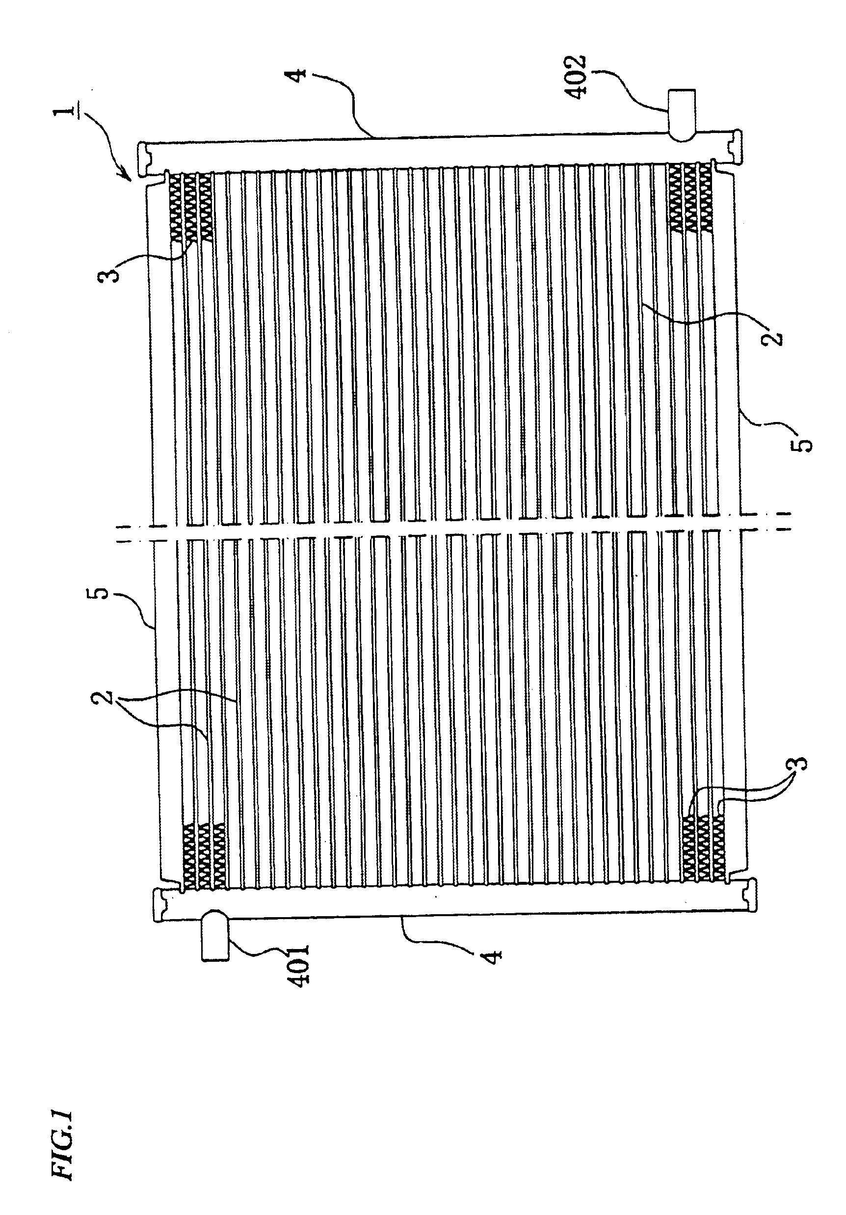
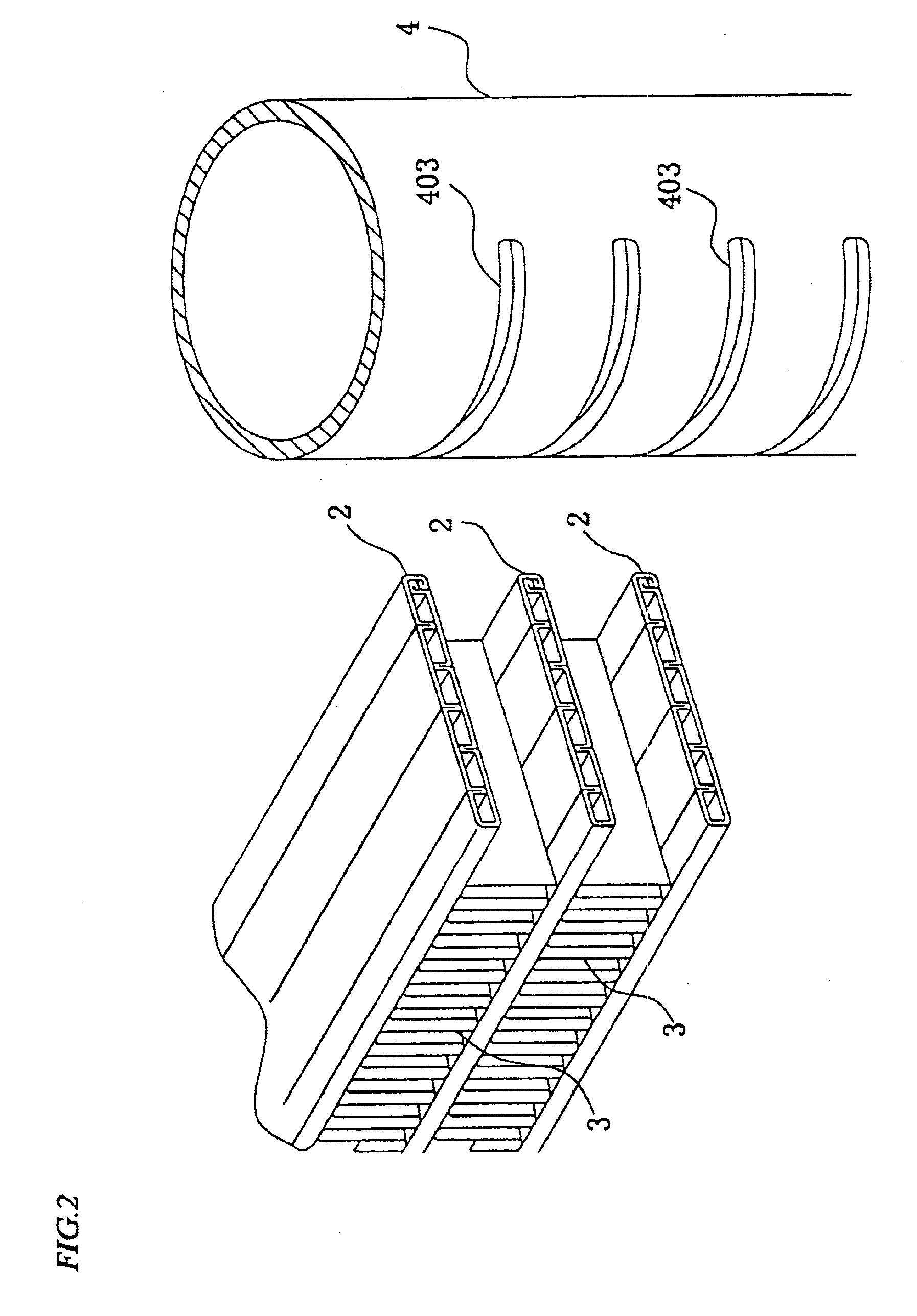
[0031]As shown in FIG. 1 and FIG. 2, a heat exchanger of this embodiment is a condenser of a refrigerating cycle for an in-car air conditioner mounted on automobiles, and has a heat exchanger core 1 configured by alternately stacking a plurality of tubes 2 and a plurality of fins 3 and connecting both ends of the tubes 2 to a pair of tanks 4.

[0032]The tanks 4 of this embodiment are cylindrical members which are provided with an inlet joint 401 and an outlet joint 402 for connecting an external pipe and holes 403 into which the ends of the tubes 2 are inserted for connection, and have their inside portioned at a prescribed width.

[0033]A medium is taken-in through the inlet joint 401, passing through the tubes 2 while heat exchanging with heat conducted to the tubes 2 and the fins 3 and discharged through the outlet joint 402.

[0034]And, side plates 5, which are reinforcin...


PUM

PropertyMeasurementUnit
lengthaaaaaaaaaa
areaaaaaaaaaaa
heat-exchange propertyaaaaaaaaaa

Abstract

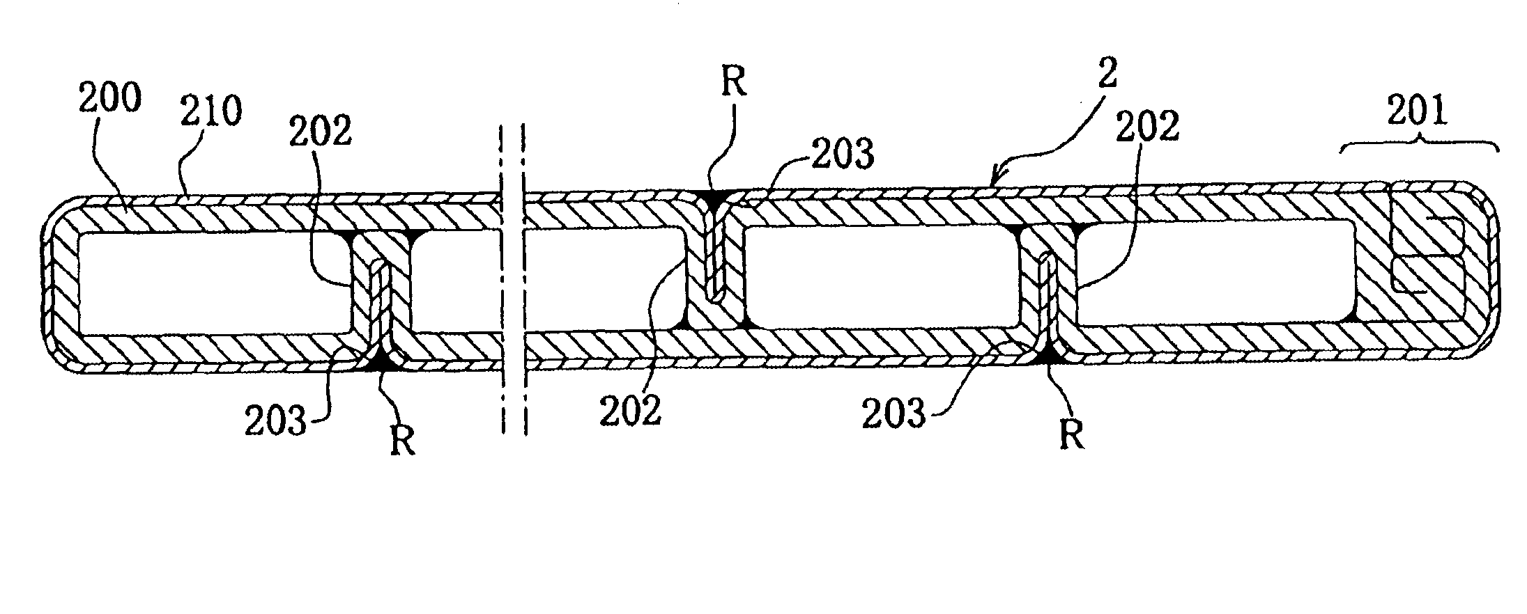
A heat exchanger comprising a heat exchange core (1) including a plurality of tubes (2) flowing a medium for heat exchange and a pair of tanks (4) to which ends of said tubes are connected, each tube formed by shaping a plate member (200) not clad with a row laminated brazing material and having a sacrifice layer (210) on an outer surface thereof and a plurality of recessed portions (203) formed on an outer surface of said sacrifice layer and filled with a brazing material (R).

Description

CROSS REFERENCE TO RELATED APPLICATIONS[0001]This is a continuation-in-part application of prior U.S. application Ser. No. 10 / 149,191 filed Jun. 10, 2002, now abandoned, which is a 371 of PCT / JP00 / 09345, filed Dec. 27, 2000.BACKGROUND OF THE INVENTION[0002]1. Technical Field[0003]The present invention relates to a heat exchanger which is provided with tubes for flowing a medium and exchanges heat of the medium with heat conducted to the tubes.[0004]2. Description of the Related Art[0005]Generally, a heat exchanger such as a condenser, an evaporator, a radiator, a heater core or the like mounted on automobiles is provided with tubes for flowing a medium, fins fitted to the tubes and tanks which are connected to the tube ends and configured to perform the heat exchange of the medium with heat conducted to the tubes and the fins.[0006]And, this type of heat exchanger is produced by assembling the tubes, fins and tanks which are made of aluminum or an aluminum alloy and heating the asse...

Claims


Application Information

Patent Timeline
Patent Type & Authority Patents(United States)
IPC IPC(8): F28F1/00B23K1/00F28D1/03F28F9/18
CPCB23K1/0012F28F9/18F28D1/0391
Inventor KATO, SOICHIAKIYAMA, SHOJI
Owner ZEXEL VALEO CLIMATE CONTROL CORP SAITAMA
Learn More