
Humidity control system for combination oven

a technology of humidity control and combination oven, which is applied in the direction of domestic stoves or ranges, furnaces, milk treatment, etc., can solve the problems of adversely affecting the efficiency of the oven, affecting the cooking time and texture of food cooked, etc., and achieves the effect of improving thermal efficiency and increasing the surface area of impinging water

Inactive Publication Date: 2006-01-17
ALTO SHAAM
View PDF13 Cites 56 Cited by
  • Summary
  • Abstract
  • Description
  • Claims
  • Application Information

AI Technical Summary

Benefits of technology

[0011]The invention thus provides a combi-oven in which relatively cool and dry air can be introduced into the cooking chamber during the cooking process. This positive inward air flow pressurizes the chamber and can cause an exhaust vent or drain to open to evacuate the hot, moist air in the chamber as needed. The positive air flow allows for more accurate humidity control in less time.
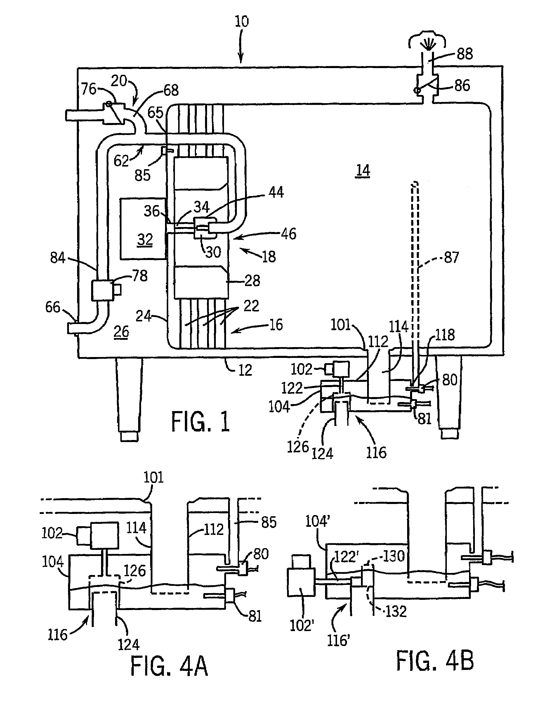
[0015]The pressure box thus operates to control water and air exchange in the cooking chamber, and thus the humidity therein. Water from the water supply pools in the pressure box before passing into the cooking chamber. Depending on the level of water in the pressure box, either water or air (entering through the vent) is passed through the intake line to the cooking chamber. The pressure box is a low-cost, highly reliable device with no moving parts.
[0016]In preferred forms, the outlet extends Into the pressure box to the working water level spaced from the bottom of the pressure box. The pressure box also can have an overflow opening, above the working water level, to which connects a drain vent / overflow line carrying away excess water or condensation that may arise in the pressure box due to relief of high or low pressure conditions in the cooking chamber. The pressure box also includes a lateral baffle spaced from the vent opening between the vent opening and the overflow opening and a pair of upright baffles spaced apart and depending down from a top wall of the pressure box. The baffles reduce noise in the pressure box and shield the vent from water.
[0017]Whether the air and water exchange in the cooking chamber is controlled by positive air displacement or the pressure box, the oven also can include a condensate tank at the cooking chamber drain. The condensate tank collects condensed vapors drained from the cooking chamber prior to leaving the oven through an outlet. The pooled water allows the hot drain water to cool somewhat, by conduction or by mixing with cooling water, before exiting the oven. It also provides a water barrier at the drain such that the cooking chamber is not in direct communication to the outside air, unless desired. This, particularly when combined with the pressure box, retains heat and steam in the cooking chamber and thus greatly increases the efficiency of the oven.
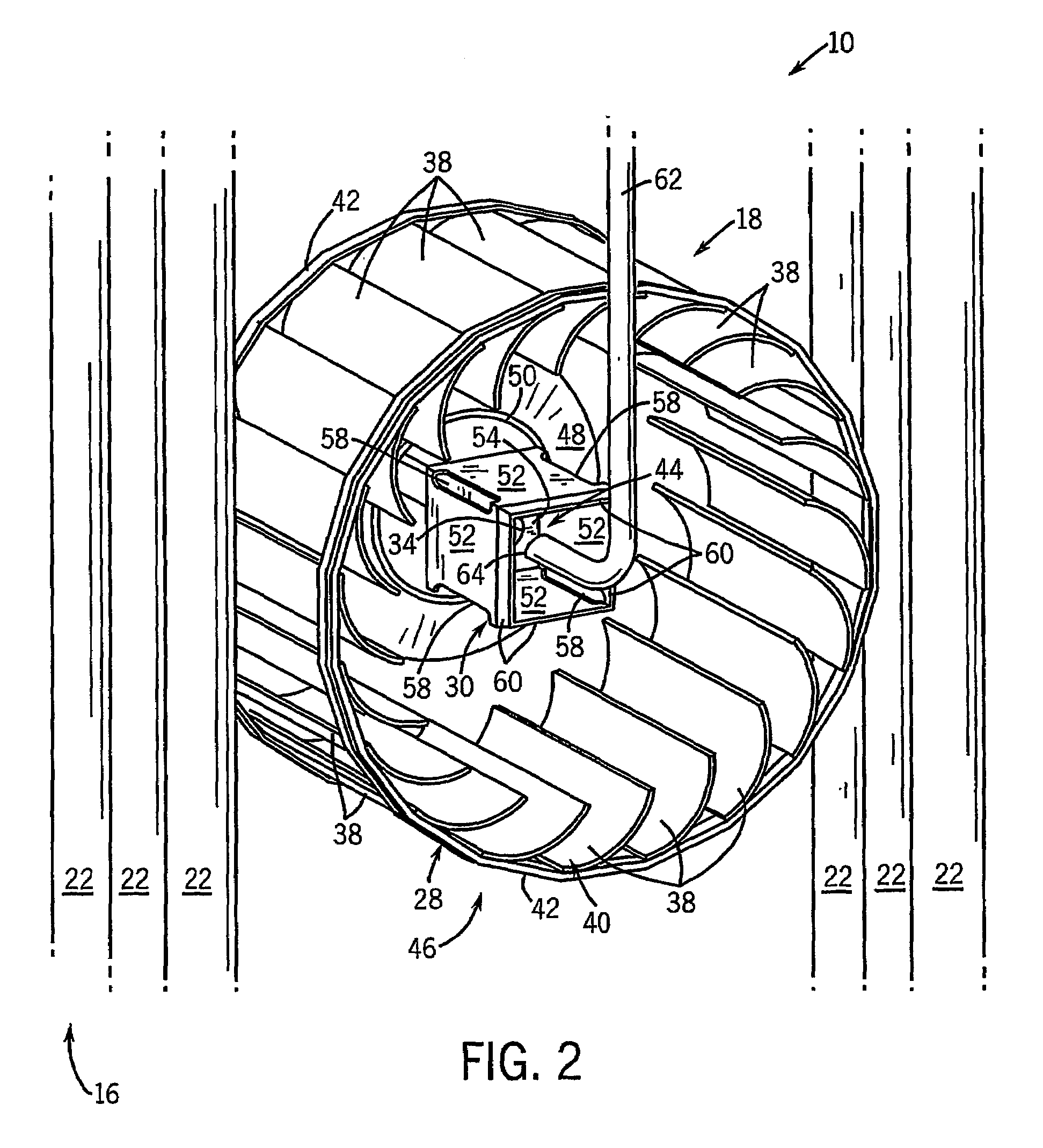
[0020]In still other preferred forms, the oven can also include an atomizer element within the fan interior receiving water from the intake line and acting to break up the water before entering the fan. The air is directed at the interior portion of the fan and the intake line is selectively controllable to pass outside water and air into the cooking chamber. The atomizer increases the surface area of the impinging water and thus improves thermal efficiency.

Problems solved by technology

This can also affect the cooking time and texture of food cooked with steam.
While this relieves the pressure imbalance, it can also cause significant temperature and humidity losses due to the interior of the cooking chamber being in direct communication with the outside air, which adversely effect the efficiency of the oven.

Method used


Image

  • Humidity control system for combination oven
  • Humidity control system for combination oven
  • Humidity control system for combination oven

Examples


Embodiment Construction

[0029]Referring to FIGS. 1–3, a combination convection and steam cooking oven 10, includes an oven enclosure 12 defining a cooking chamber 14 for heating foodstuffs. The oven 10 also includes a heating system 16, an atomizer assembly 18 and a humidity control system 20. The heating system 16 generally includes burners 21 which heat gas circulated through heating elements 22 preferably consisting of metallic conduits. Preferably, the heating elements 22 include two sets of three conduits extending vertically in close proximity to a partition wall 24 of the oven enclosure 12 separating the cooking chamber 14 from an electronics compartment 26. It should be noted that the heating elements 22 could also be suitable solid resistive heating elements.

[0030]Referring to FIGS. 1 and 2, the atomizer assembly 18 includes a motor-operated fan 28 and an atomizer cup 30 both of which are disposed between the heating elements 22, three of the heating elements 22 being on each side of the atomizer ...


PUM


Abstract

A combination oven for the preparation of food has a cooking chamber containing heating elements, a fan and an atomizer for radiant, convective or steam cooking. The humidity within the cooking chamber is controlled by a water valve and either by forcing dry air into the cooking chamber and venting the humid air or by using a pressure box. Without any moving parts, the pressure box controls air exchange of the cooking chamber according to the level of water within the pressure box and the pressure in the cooking chamber. The oven has a condensate tank to collect condensation drained from the cooking chamber. The pressure box and condensate tanks form water barriers effectively isolating the cooking chamber from the vent and drain during cooking until venting is required.

Description

CROSS-REFERENCE TO RELATED APPLICATIONS[0001]This application claims the benefit of U.S. provisional application Ser. No. 60 / 318,249, filed Sep. 7, 2001.STATEMENT OF FEDERALLY SPONSORED RESEARCH / DEVELOPMENT[0002]Not Applicable.BACKGROUND OF THE INVENTION[0003]The present invention relates to food preparation ovens, and in particular, to combination convection and steam ovens.[0004]Combination ovens provide the ability to cook foods using steam, hot air convection or both steam and convection. A motor driven fan is ordinarily used to circulate air within a cooking chamber past electrical heating elements or gas heat exchange tubes. To produce steam within the cooking chamber, a water line feeds water into the cooking chamber near the heating elements to vaporize the water.[0005]Combination ovens typically feed water to the center of the fan so that the water is drawn through the fan. Contact of the water with the fan blades separates the water into small droplets providing a larger o...

Claims


Application Information

Patent Timeline
IPC IPC(8): A21B1/24A21B1/26A21B3/04F24C1/00F24C15/32
CPCF24C15/327A21B3/04
Inventor HANSEN, WILLIAM JBARTELICK, JAN
Owner ALTO SHAAM
Learn More