
Load balancing method and system based on estimated elongation rates

a load balancing and estimated elongation technology, applied in the field of load balancing methods and systems based on estimated elongation rates, can solve the problems of not necessarily ensuring that such individual optimization systems are directly linked to the optimization of the whole system, the load state of each computer that is used to determine the load balancing cannot be sufficiently grasped, and the merit of dynamic control will mostly be lost. , to achieve the effect of keeping the system-wide mean and the variation of respons

Inactive Publication Date: 2006-01-10
NEC CORP
View PDF26 Cites 108 Cited by
  • Summary
  • Abstract
  • Description
  • Claims
  • Application Information

AI Technical Summary

Benefits of technology

[0021]Another object of the present invention is to provide a low-overhead dynamic load balancing method capable of keeping the system-wide mean and variation of response times small by balancing the transaction processing load among the computers.

Problems solved by technology

However, there is not necessarily a guarantee that such individual optimization system is directly linked to the optimization of the whole system.
However, the merit of dynamic control will mostly be lost by the use of the mean value of the whole, if it is of single type but the variation of job characteristics is wide, or in the case where multiple types of processing providing different characteristics are mixed, which appears much closer to reality.
A first problem of the prior arts is that the load state of each computer that is used to determine the load balancing cannot be sufficiently grasped.
However, it cannot be said that they reflect sufficiently the system congestion state, taking into consideration job characteristics including the CPU / input output use rate in a group of in-process transactions at that time.
However, the trend has been to reduce the collection frequency because the overhead of data collection increases in the distributed computer system.
A second problem of the prior arts is that the system-wide optimization on average of response time and minimization of variations cannot be always obtained.
However, such an individual optimization scheme does not necessarily ensure the system-wide optimization.

Method used


Image

  • Load balancing method and system based on estimated elongation rates
  • Load balancing method and system based on estimated elongation rates
  • Load balancing method and system based on estimated elongation rates

Examples


first embodiment

1.1 System configuration

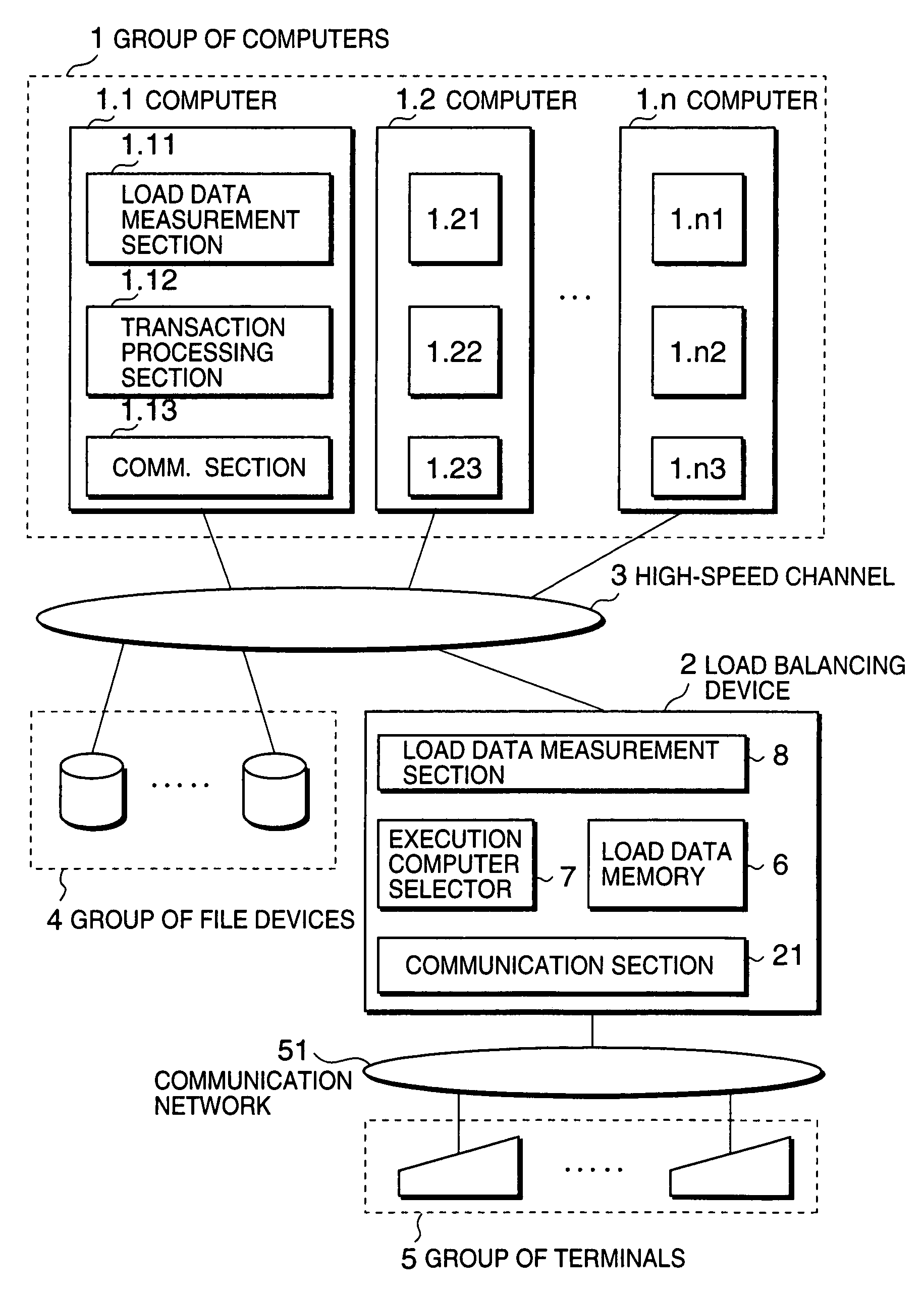
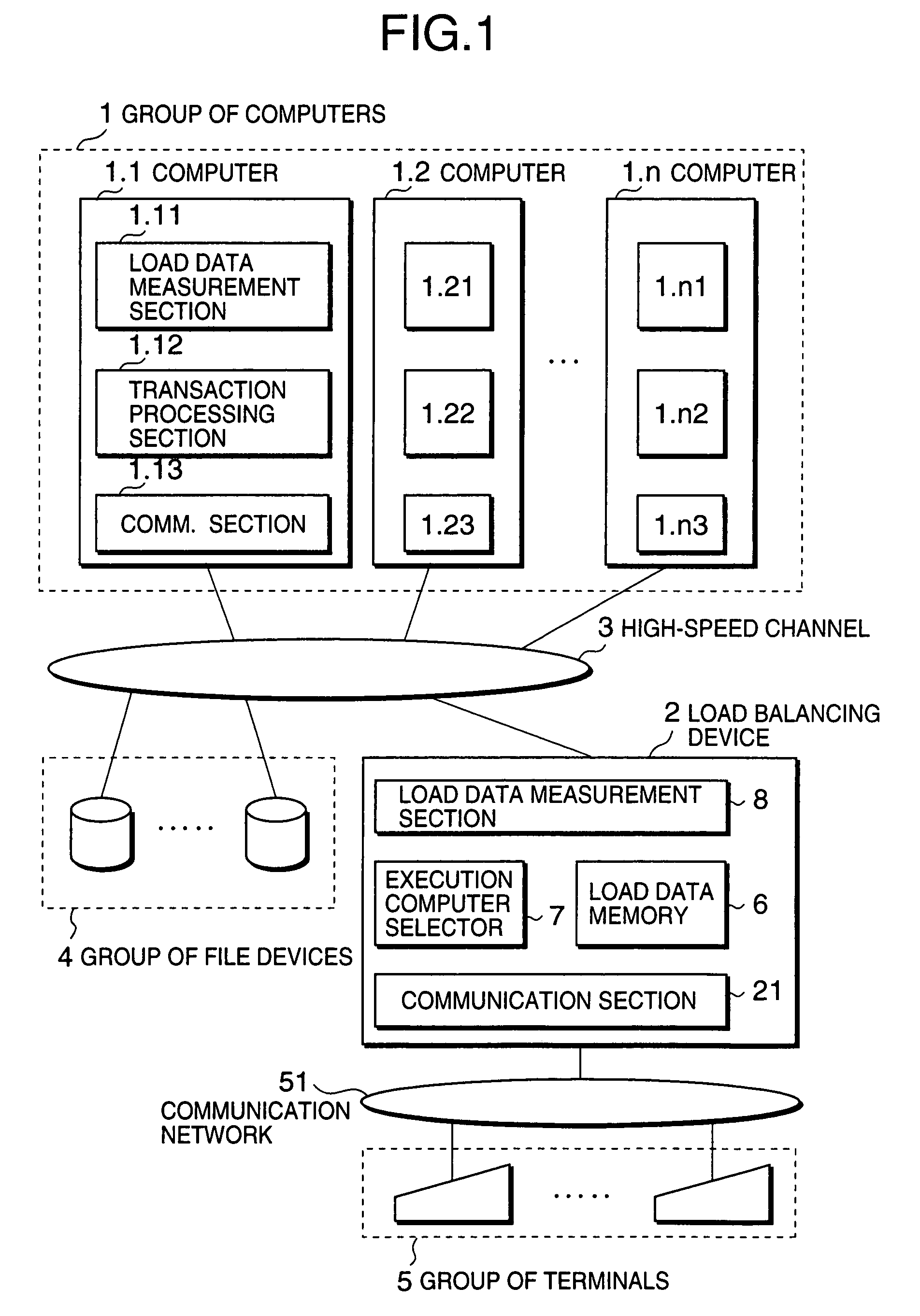
[0050]Referring to FIG. 1, a computer group 1 is composed of n computers 1.1 through 1.n (generally denoted by 1.x), each of which is a program-controlled computer. The computer group 1 is connected to a load balancing device 2 and a file device group 4 through a high-speed channel 3. The load balancing device 2 is further connected to a terminal group 5 through a communication network 51.

[0051]In the computer group 1, a computer 1.x (x=1, 2, . . . , or n) includes a load data measurement section 1.x1, a transaction processing section 1.x2, and a communication section 1.x3. The transaction processing section 1.x2 includes a plurality of job processing processes (not shown).

[0052]The load balancing device 2 includes a communication section 21, a load data memory 6, an execution computer selector 7, and a load data measurement section 8. The computers 1.1 to 1.n do not share a main memory but the file device group 4 via the high-speed channel 3 with equivalent ...

second embodiment

[0104]Now, a second embodiment of the present invention will be described in detail.

2.1 System Configuration

[0105]Referring to FIG. 6, the second embodiment of the present invention is different, as for the composition, from the first embodiment in that the terminal devices of the terminal group 5 are connected directly to the computers 1.1 through 1.n via the communication network 51 without the load balancing device 2 and that a switch and storage fabric 10 is connected to the computers 1.1 through 1.n.

[0106]Since the load balancing device 2 is removed, a computer 1.i includes a load data memory 6.i, an execution computer selector 7.i and load data measurement section 8.i in addition to the load data measurement section 1.i1, the transaction processing section 1.i2 and the communication section 1.i3. These respective sections may be realized by running respective ones of programs stored in a recoding media (not shown) as in the first embodiment.

[0107]A single transaction is proce...

third embodiment

[0130]A third embodiment of the present invention will be described in detail with reference to FIGS. 7–9.

3.1 System Configuration

[0131]As shown in FIG. 7, the third embodiment of the present invention is different in system configuration from the second embodiment. In the third embodiment, an interim load balancing device 25 is provided, through which the terminal group 5 is connected to each of the computers 1.1–1.n.

[0132]A single transaction is processed as described below. A transaction processing, request message is sent from a terminal device belonging to the terminal group 5, and is received by the interim load balancing device 25 via the communication network 51. The interim load balancing device 25, when receiving the transaction processing request message, determines an interim destination computer according to static / quasi-static decision scheme or without using dynamic information in the dynamic load balancing control. The details of the static / quasi-static decision sch...


PUM


Abstract

A dynamic load balancing method allowing a transaction processing load is balanced among computers by using estimated elongation rates is disclosed. In a system composed of a plurality of computers for processing transaction processing requests originating from a plurality of terminals, elongation rates of processing time for respective ones of the computers are estimated, where an elongation rate is a ratio of a processing time required for processing a transaction to a net processing time which is a sum of CPU time and an input / output time for processing the transaction. After calculating load indexes of respective ones of the computers based on the estimated elongation rates, a destination computer is selected from the computers based on the load indexes, wherein the destination computer having a minimum one among the load indexes.

Description

BACKGROUND OF THE INVENTION[0001]1. Field of the Invention[0002]The present invention relates to a system for executing transaction processing by sharing load among a plurality of computers, nodes, or processors, that are connected to each other to form a relatively close group such as a cluster, and more particularly to a system and method for balancing transaction processing loads among the computers.[0003]2. Description of the Related Art[0004]In a system including a plurality of processing devices (computers), a load balancing method is designed to provide the maximum performance of the system by appropriately distributing a large number of successive arrivals of messages each requiring small-scale processing over these multiple computers. Since the processing required for each message is small in scale, a computer to execute the processing of a message is generally decided on arrival and the selected computer performs and finishes the processing without migrating it to another ...

Claims


Application Information

Patent Timeline
IPC IPC(8): G06F9/46G06F9/50G06F15/177
CPCG06F9/505G06F2209/5019
Inventor KUBO, HIDEHITO
Owner NEC CORP
Learn More