
Recording medium discriminating method and recording apparatus

a discriminating method and recording medium technology, applied in the direction of digitally marking record carriers, digital output to print units, instruments, etc., can solve the problems of inability to obtain the quality demanded by users in some cases, difficulty in accurately and the related art described above, etc., to achieve the effect of improving the accuracy of discriminating between photographic glossy paper and glossy film relationships

Inactive Publication Date: 2006-01-10
CANON KK
View PDF8 Cites 15 Cited by
  • Summary
  • Abstract
  • Description
  • Claims
  • Application Information

AI Technical Summary

Benefits of technology

This approach enables high-accuracy discrimination of recording media types, improving image quality and preventing paper jams by correctly setting recording conditions without the need for mechanical movement of the sensor or medium, and enhancing the differentiation between previously challenging media like glossy film and photographic glossy paper.

Problems solved by technology

In so doing, if the user erroneously sets the type of the recording medium and the recording mode by mistake, a recording image having the quality demanded by the user cannot be obtained in some cases.
The related art described above, however, has problems as follows.
As seen from FIG. 36, it is difficult to accurately discriminate plain paper and ink-jet coated paper from the relationships between the recording media and two reflected-light components, i.e., the specular reflection light and the diffuse reflection light.
The coating of calcium carbonate is effective in increasing the whiteness of the recording medium, but it becomes difficult to discriminate plain paper having high whiteness because of a coating of calcium carbonate from ink-jet coated paper.
Thus, in a conventional system employing reflection optical sensors for measuring the intensity of the specular reflection light and the intensity of the diffuse reflection light, it is difficult to discriminate plain paper and ink-jet coated paper from each other.
This leads to a serious problem in an ink-jet recording apparatus in which recording conditions, such as the amount of ejected ink and the number of scans, i.e., passes, of a recording head for recording a one-line image differ depending on the type of the recording medium.
In the above-mentioned two types of recording media, particularly, a significant difference exists in the recording conditions and hence a serious image quality problem results as well.
Also, in electrophotographic recording apparatuses other than the ink-jet recording apparatus, if users mistakenly place ink-jet coated paper instead of plain paper in a cassette storing the recording medium, there is a risk that the recording medium will wrap around the fusing roller and cause a paper jam.
In other words, the necessity of accurately discriminating various types of recording media for ink-jet printing, which are widely put into the market, is a problem not restricted to the field of ink-jet recording apparatuses.
However, it is difficult to discriminate several types of recording media used in high quality image recording.
More specifically, while attention has been recently focused on photographic glossy paper, which is a recording medium capable of recording an image with a quality comparable to that of a photograph printed on photographic paper, and on a glossy film using white PET, etc. as a base, it is difficult to accurately discriminate those two types of recording media because both recording media have high gloss values.

Method used


Image

  • Recording medium discriminating method and recording apparatus
  • Recording medium discriminating method and recording apparatus
  • Recording medium discriminating method and recording apparatus

Examples


first embodiment

(First Embodiment)

[0072]A first embodiment implementing the present invention will be described below in detail with reference to the drawings. Each of the elements shown in block outline in the figures is well known per se, and a specific type of construction is not critical to carrying out the invention or to a disclosure of the best mode for carrying the invention.

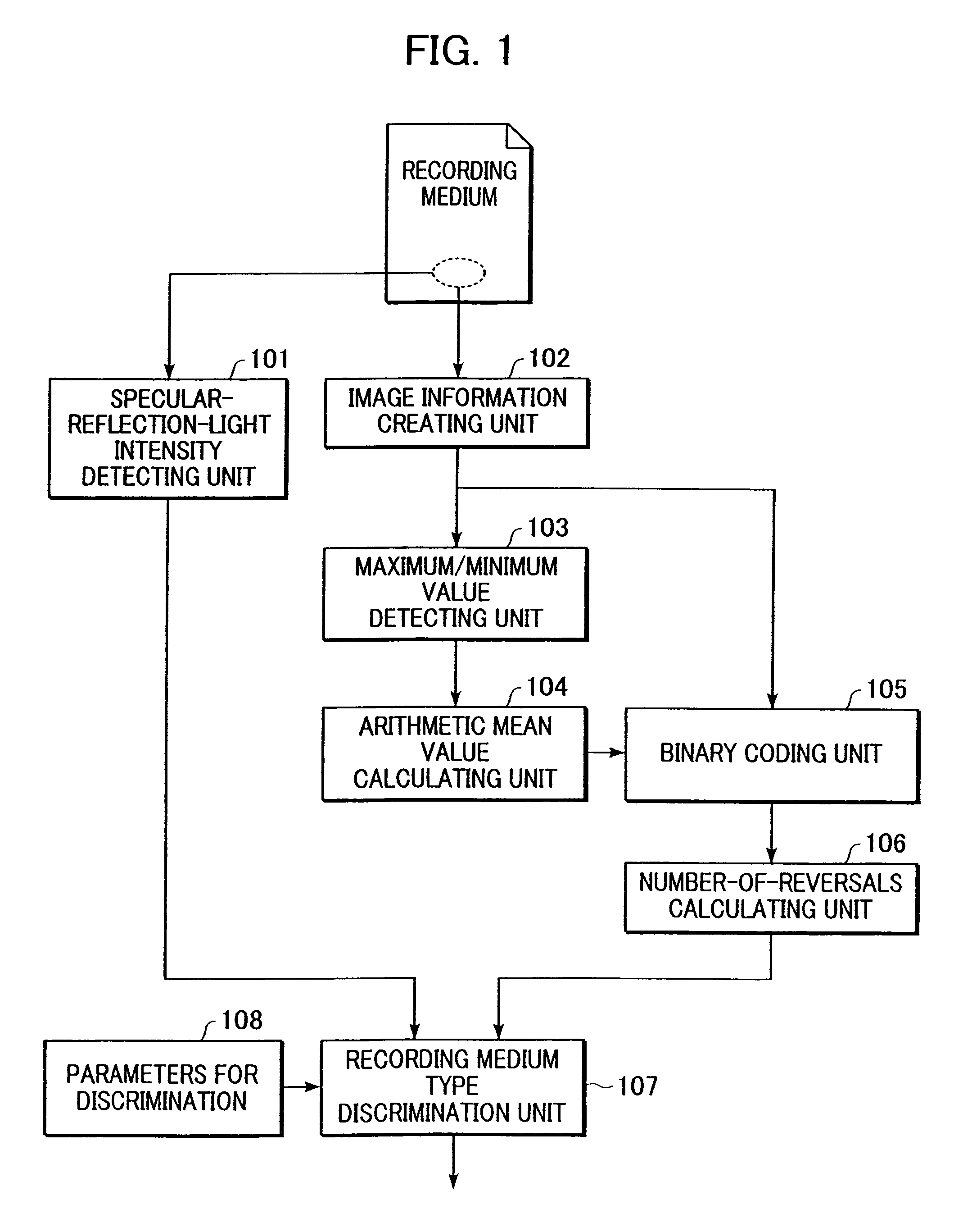
[0073]FIG. 1 is a functional block diagram showing a recording medium discriminating method according to a first embodiment of the present invention.

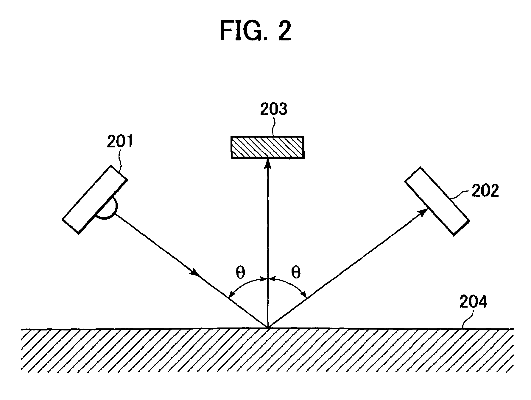
[0074]Referring to FIG. 1, a specular-reflection-light intensity detecting unit 101 detects the intensity of one component of reflected light from a surface of a recording medium, which is illuminated by a light source, i.e., the intensity of a specular reflection light having reflected at an angle of reflection equal to an angle of incidence is detected.

[0075]An image information creating unit 102 creates image information from an arbitrary small area of the recording medi...

second embodiment

(Second Embodiment)

[0152]A second embodiment implementing the present invention will be described below in detail with reference to the drawings.

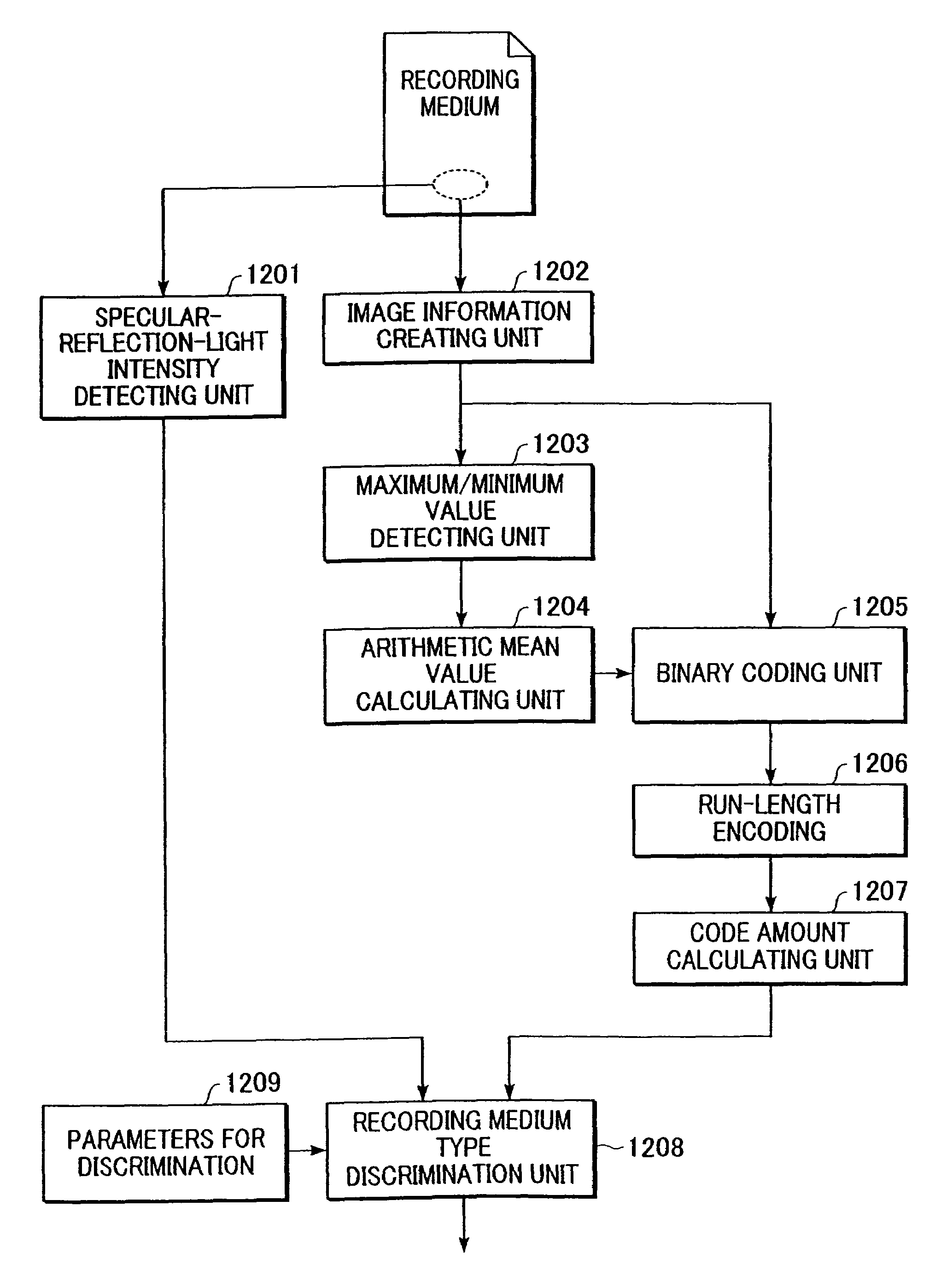
[0153]While in the first embodiment the type of the recording medium is discriminated using the intensity of the specular reflection light and the number of reversals after the binary coding, a recording medium discriminating method of this second embodiment discriminates the type of the recording medium by using the intensity of the specular reflection light and a run-length code amount.

[0154]FIG. 12 is a functional block diagram showing the recording medium discriminating method according to the second embodiment.

[0155]A specular-reflection-light intensity detecting unit detects the intensity of one component of reflected lights from a surface of a recording medium, which is illuminated by a light source, i.e., the intensity of a specular reflection light having reflected at an angle of reflection equal to an angle of incidence is detecte...

third embodiment

(Third Embodiment)

[0183]A third embodiment implementing the present invention will be described below in detail with reference to the drawings.

[0184]A recording medium type discriminating method realizing this third embodiment is featured in discriminating the type of the recording medium based on the intensity of the specular reflection light and the number of isolated pixels. A process flow and a discrimination flow are substantially the same as those in the first embodiment, and hence a description thereof is omitted here.

[0185]FIG. 17 is a functional block diagram showing the recording medium discriminating method according to the third embodiment.

[0186]A specular-reflection-light intensity detecting unit 1701 detects the intensity of one component of reflected lights from a surface of a recording medium, which is illuminated by a light source, i.e., the intensity of a specular reflection light having reflected at an angle of reflection equal to an angle of incidence is detected...


PUM

PropertyMeasurementUnit
brightnessaaaaaaaaaa
gloss levelaaaaaaaaaa
glossaaaaaaaaaa

Abstract

Discrimination of the type of a recording medium with high accuracy is obtained by using the intensity of a specular reflection light from the recording medium and a feature of the recording medium surface derived from an image of the recording medium surface as discrimination parameters. In particular, the accuracy in discrimination between plain paper and ink-jet coated paper and between photographic glossy paper and a glossy film is improved. Also, the type of the recording medium is discriminated based on a detected value of the intensity of the specular reflection light from the recording medium and a parameter representing surface conditions of the recording medium which is derived from an image information made up of a plurality of pixels corresponding to a predetermined area of the recording medium surface.

Description

BACKGROUND OF THE INVENTION[0001]1. Field of the Invention[0002]The present invention relates to a recording medium discriminating method for discriminating the type of a recording medium, a recording apparatus having a function of discriminating the type of a recording medium, a program for executing the discrimination as to the type of a recording medium, and a storage medium storing the program. More particularly, the present invention relates to a technique for discriminating the type of a recording medium from image information regarding a surface of the recording medium.[0003]2. Description of the Related Art[0004]Hitherto, various types of output devices, such as electrophotographic, wired-dot, and ink-jet devices, have been practiced as output devices of printing systems in which a color image is formed by attaching colored toners or inks to a recording surface of a recording medium and then ejecting the recording medium having the color image recorded thereon.[0005]Of those...

Claims


Application Information

Patent Timeline
Patent Type & Authority Patents(United States)
IPC IPC(8): B41J2/01B41J11/00B41J29/46B65H7/14G01N21/57G06T1/00G06T7/00
CPCG01N21/57B41J11/009
Inventor TSUJIMOTO, TAKUYA
Owner CANON KK
Learn More